Hall Bulldog 3D Modeling: Final Report

Part of The Hall Bulldog Project — documenting Bob Hall's 1932 Thompson Trophy racer.
Explore the Project →This is the fifth and final report from Mirco Pecorari of Aircraft Studio Design, providing comprehensive documentation of the Hall Bulldog 3D modeling project. This report covers adding surface details, applying the authentic paint scheme, and creating photorealistic renders with weathering effects.
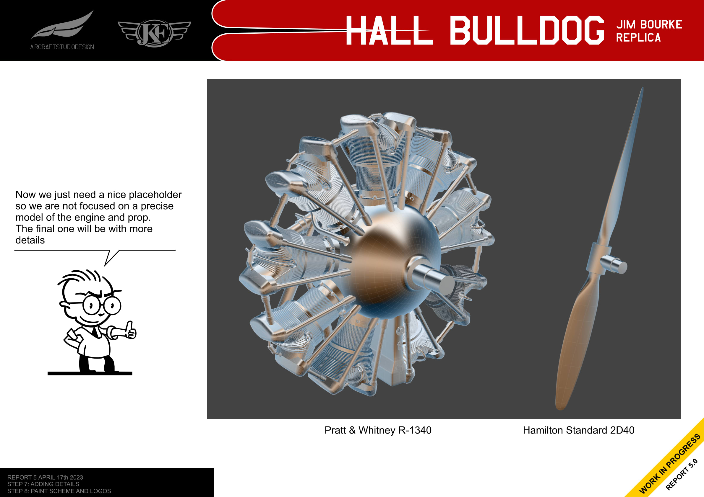
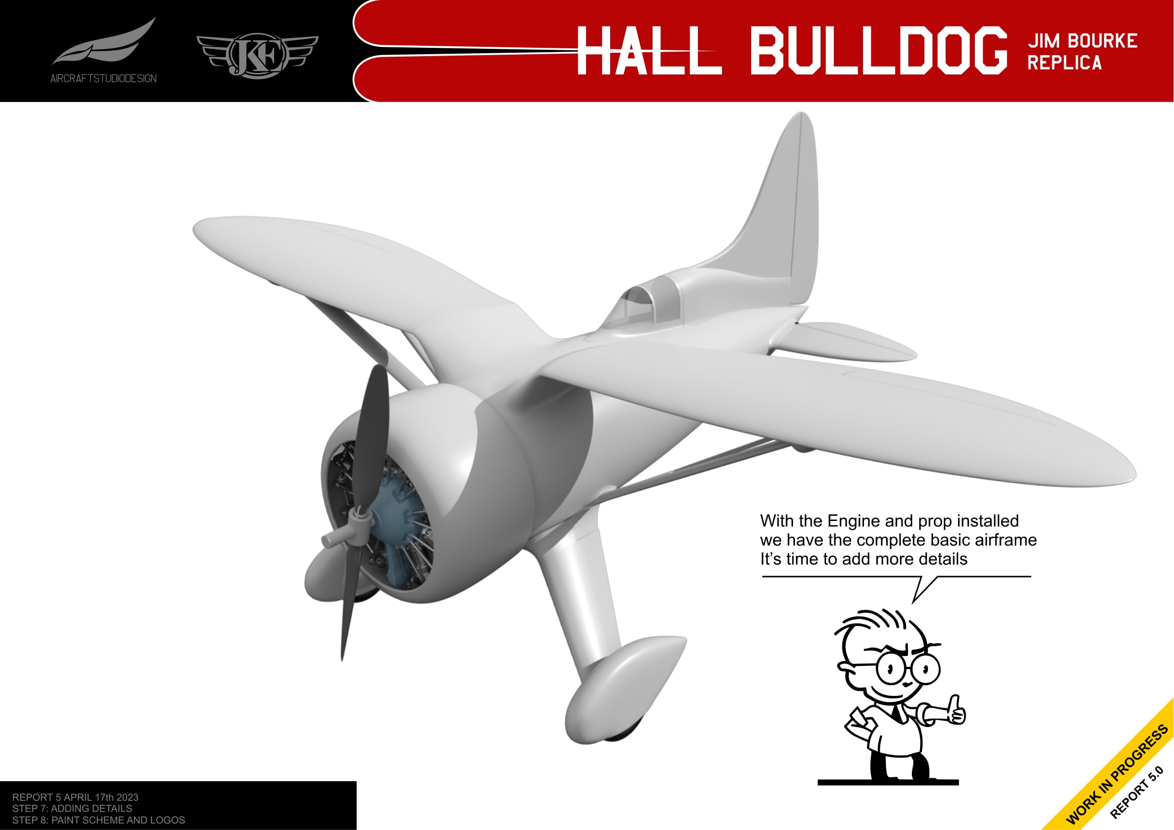
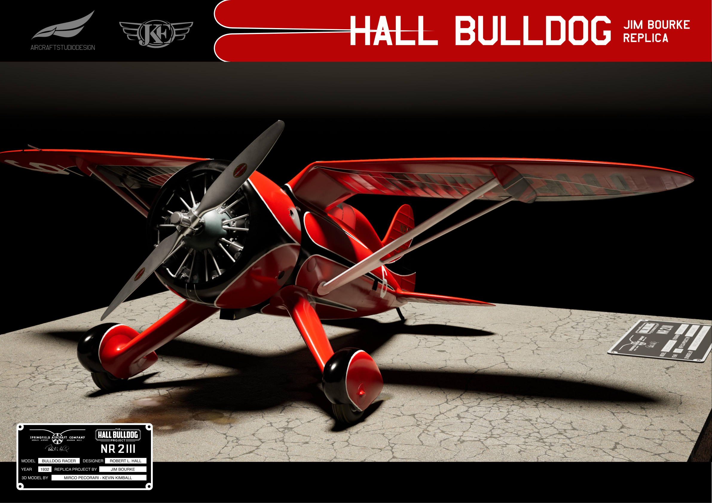
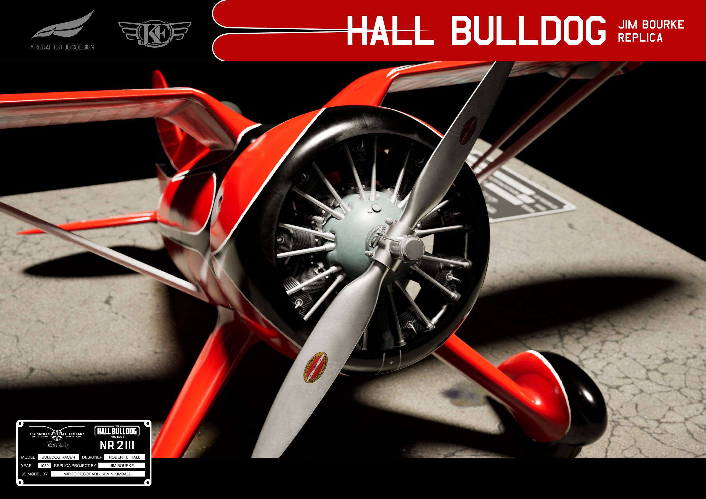
Engine and Propeller Complete
With the Pratt & Whitney R-1340 engine and Hamilton Standard 2D40 propeller installed, the basic airframe was complete. It was time to add the smaller details that would bring the model to life.
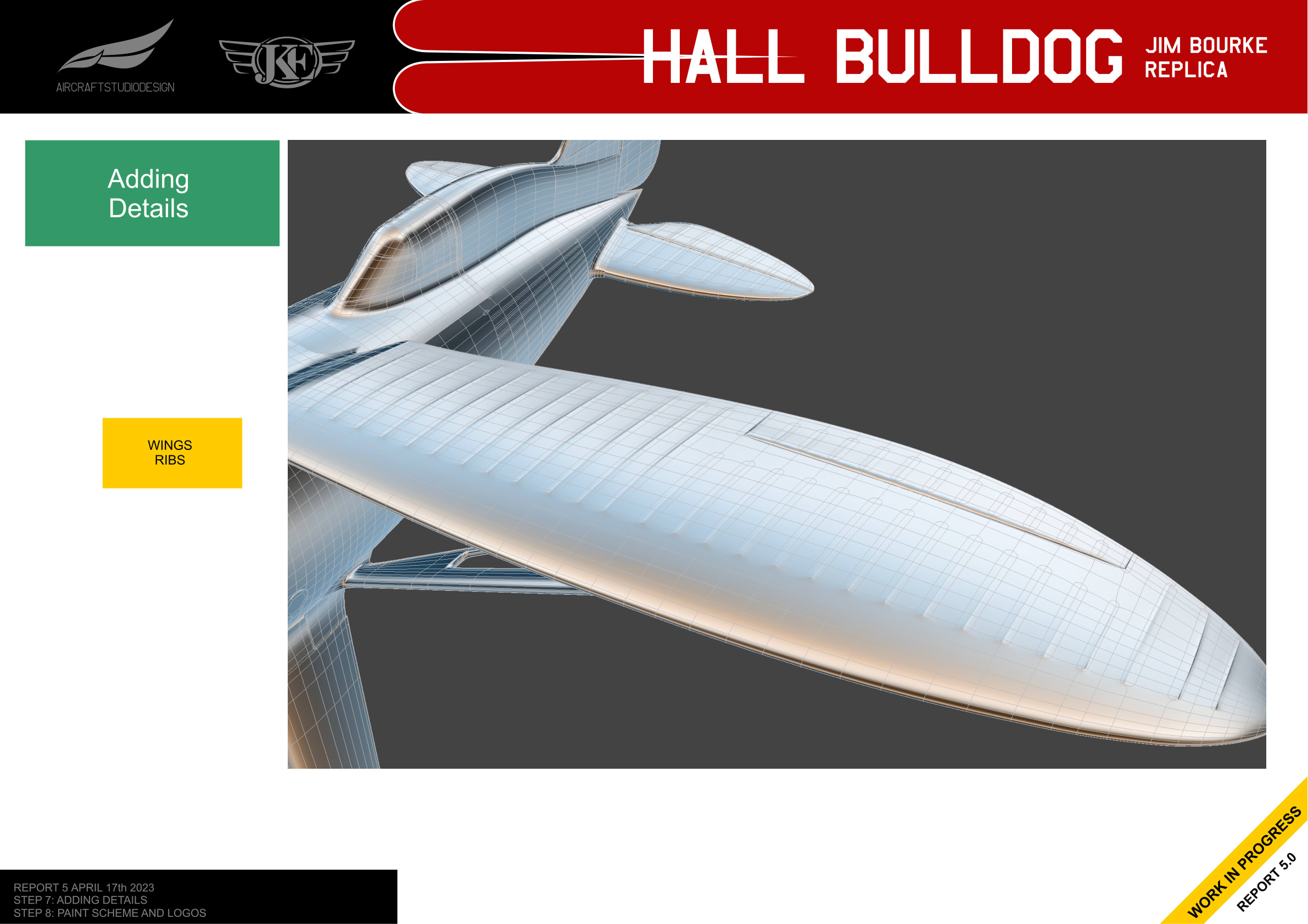
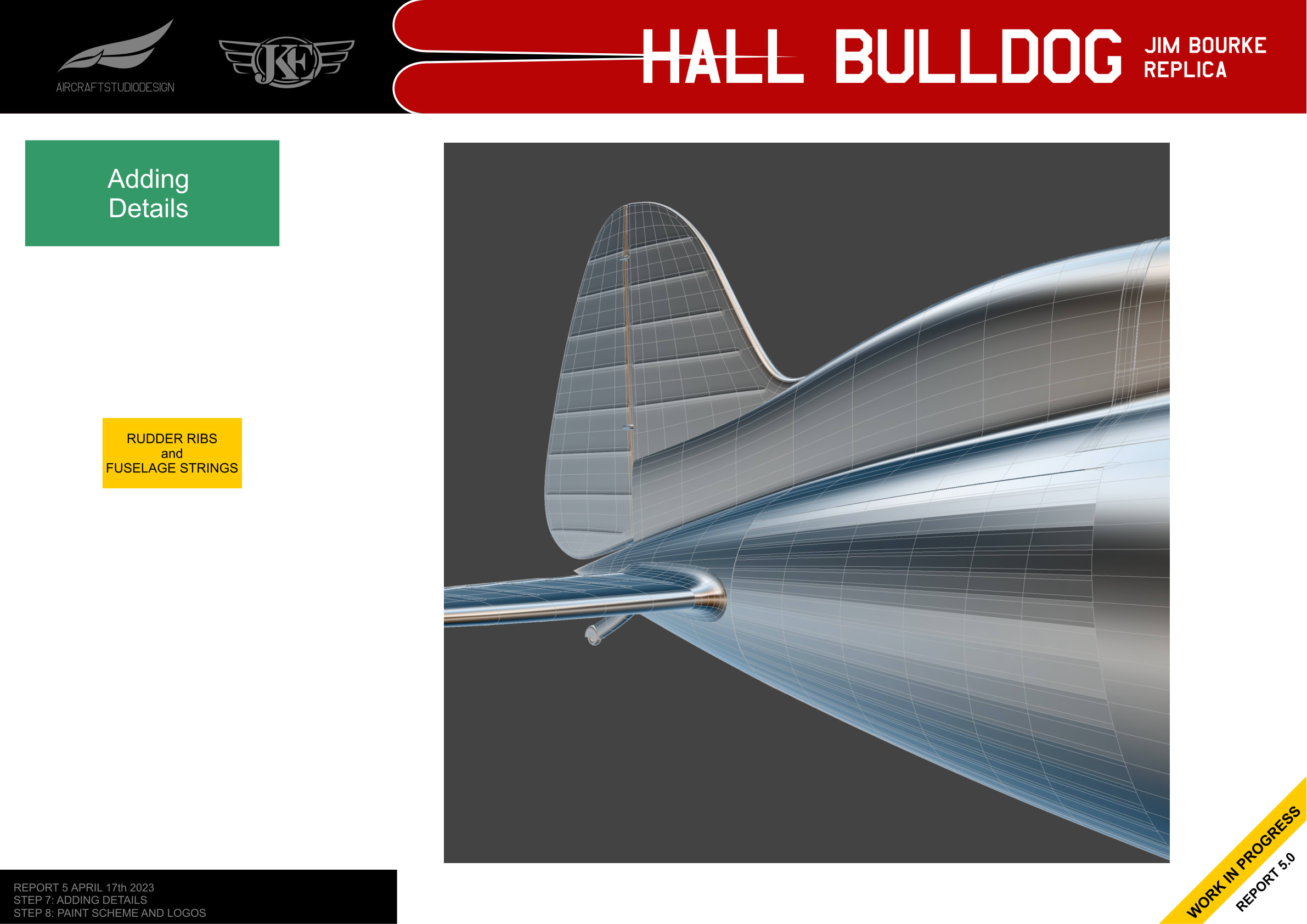
Adding Details
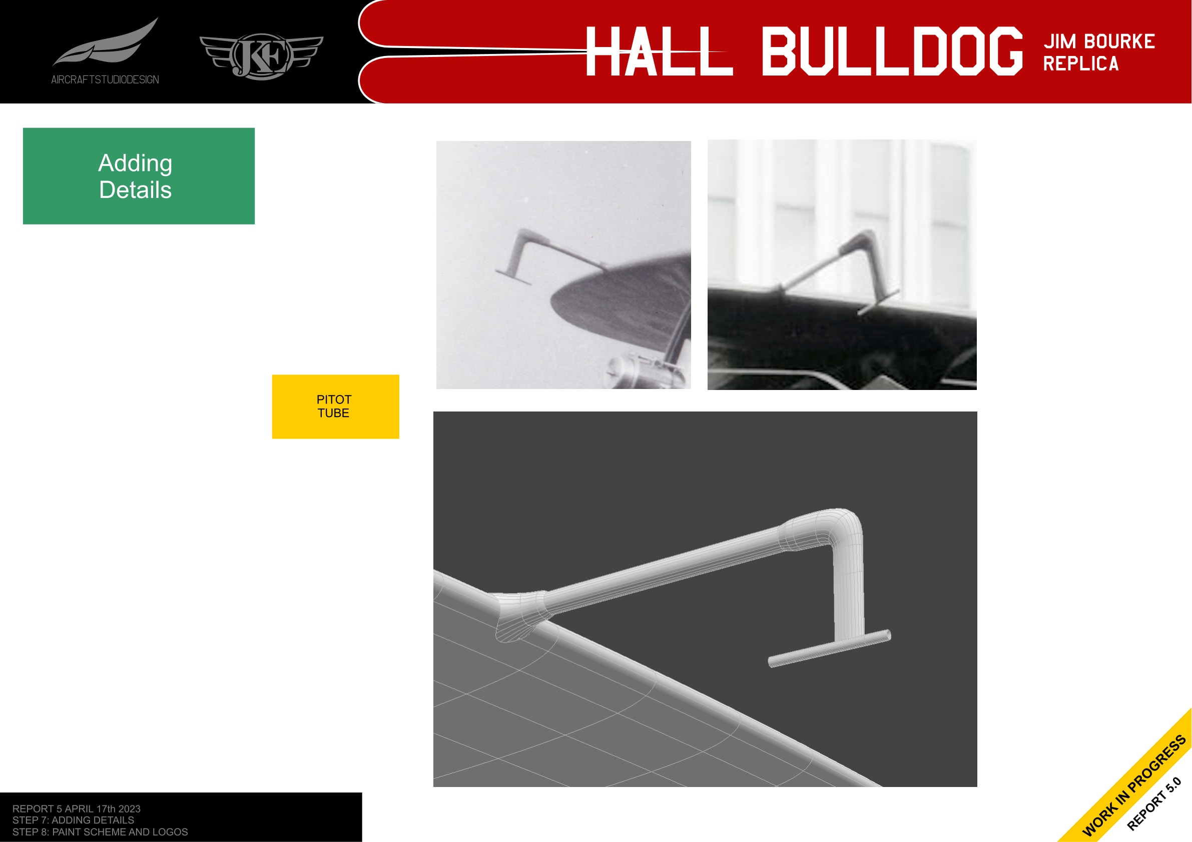
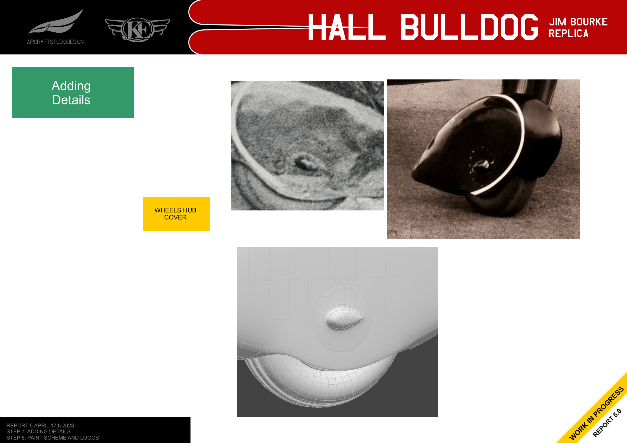
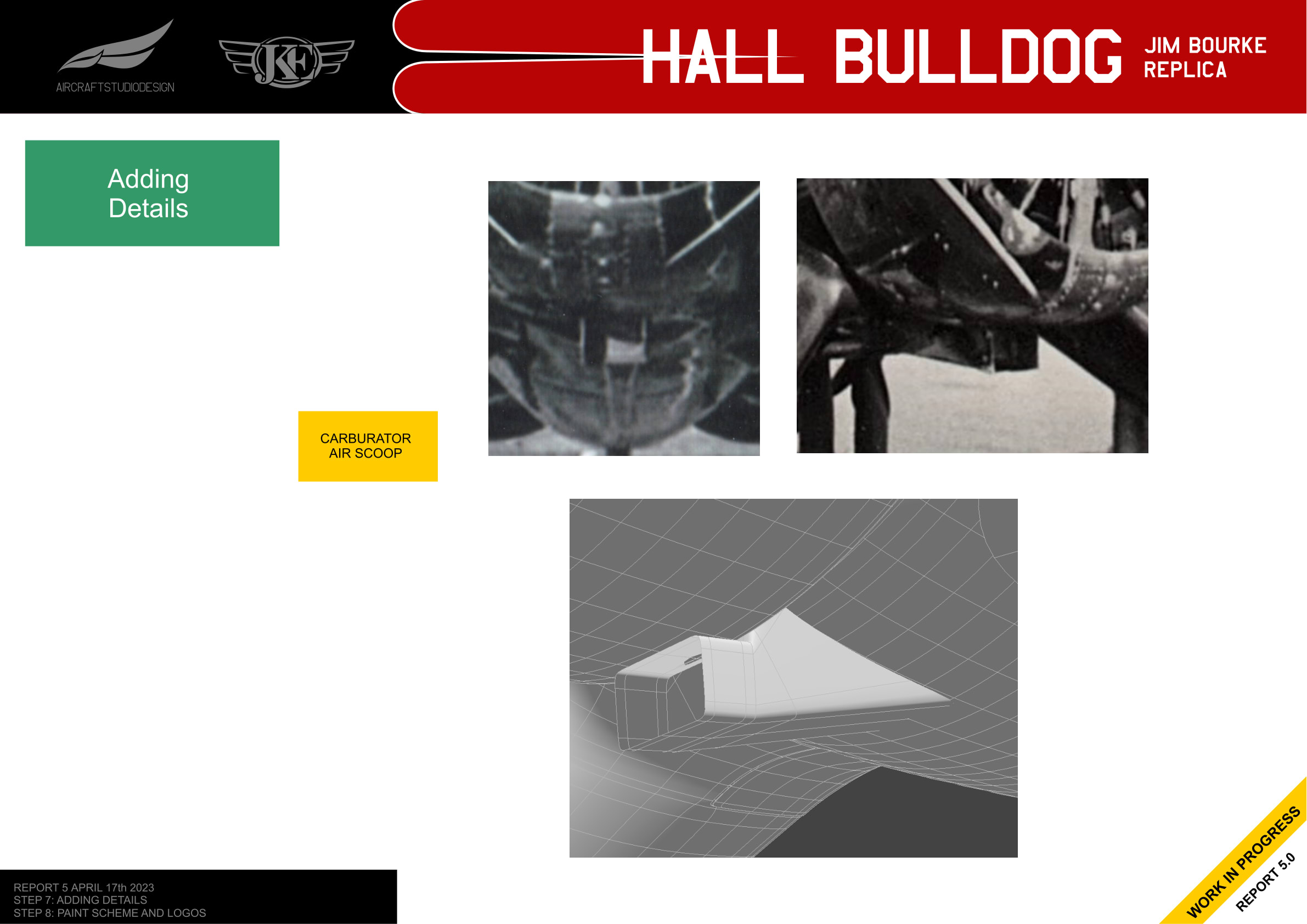
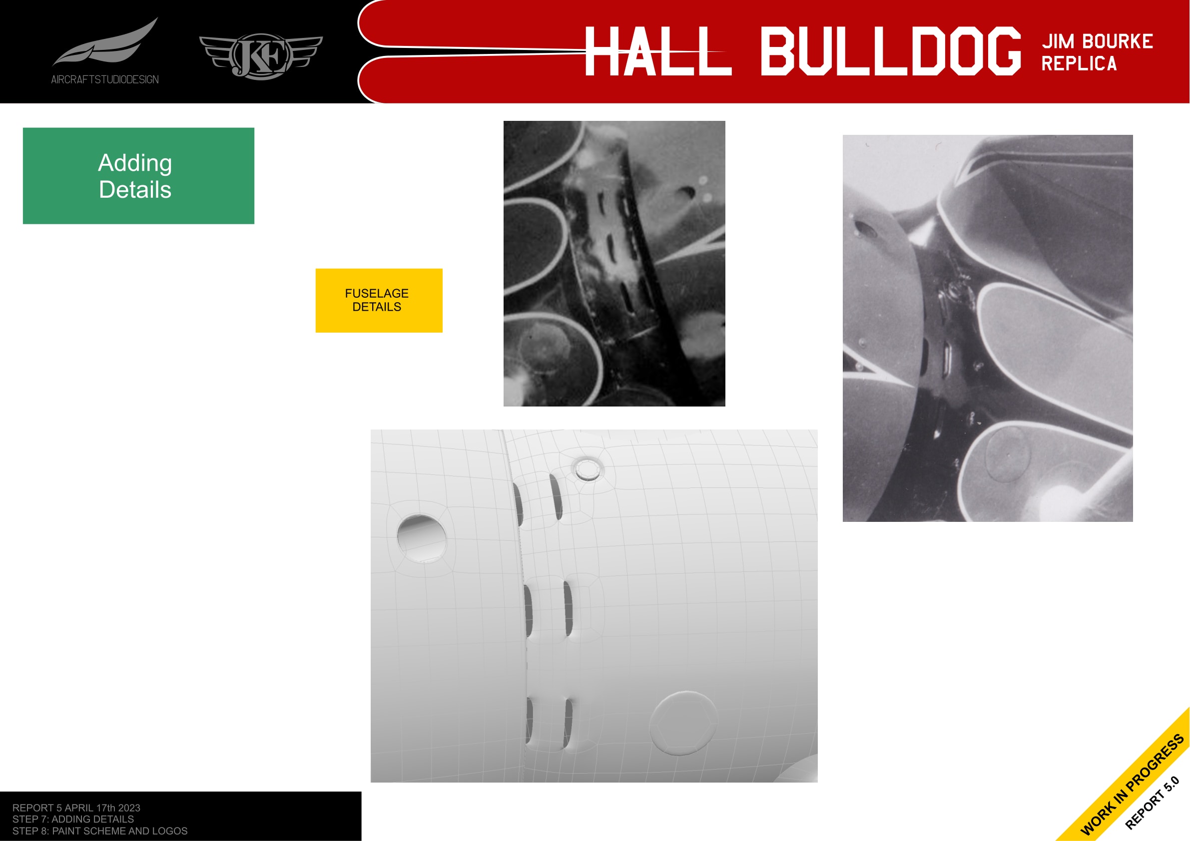
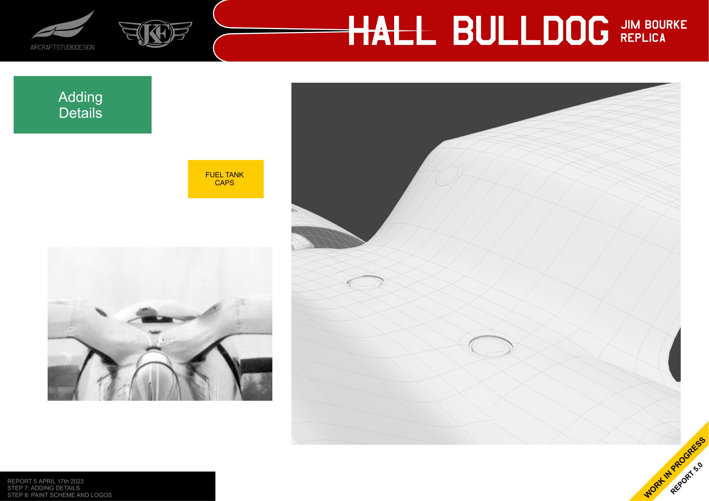
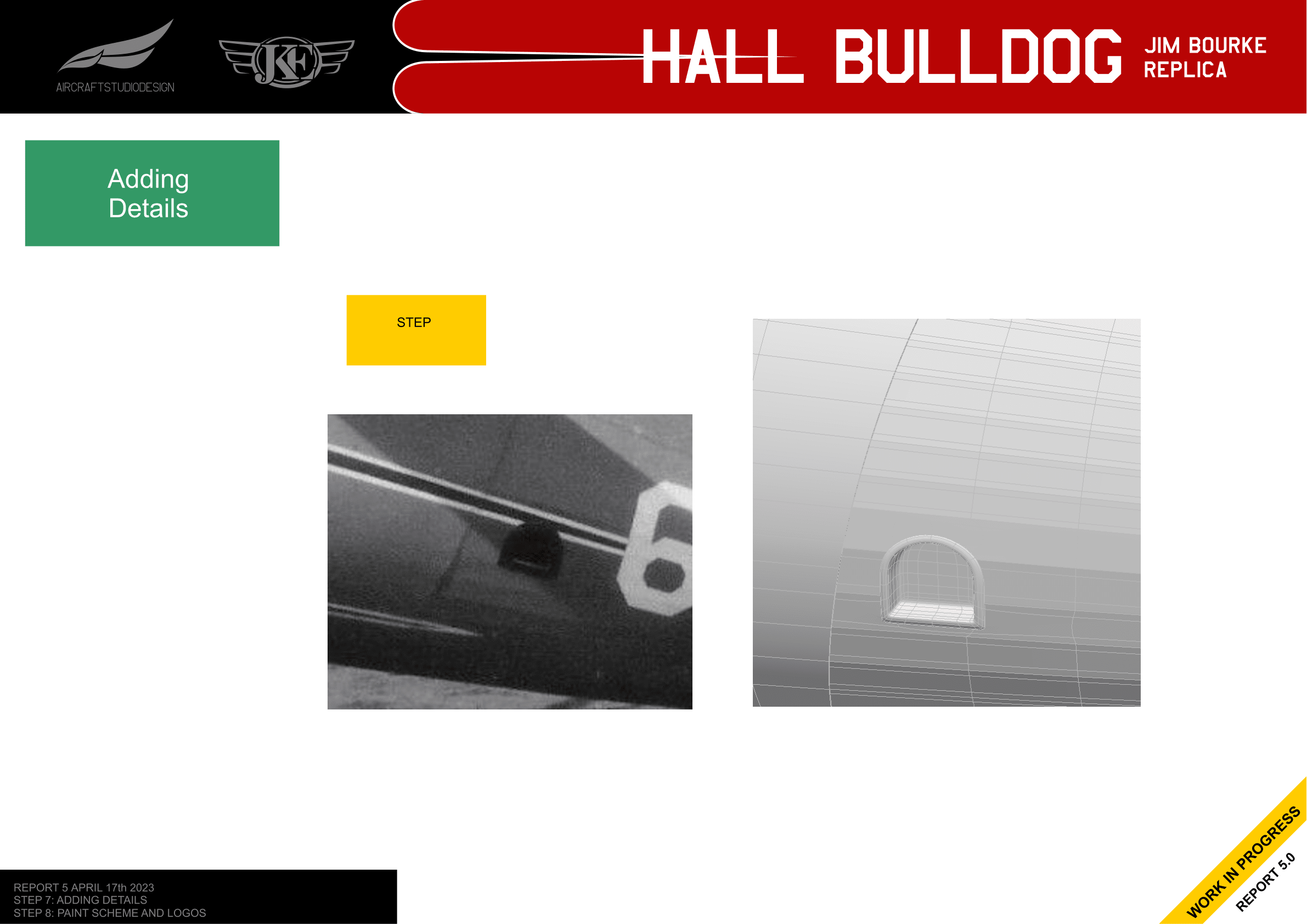
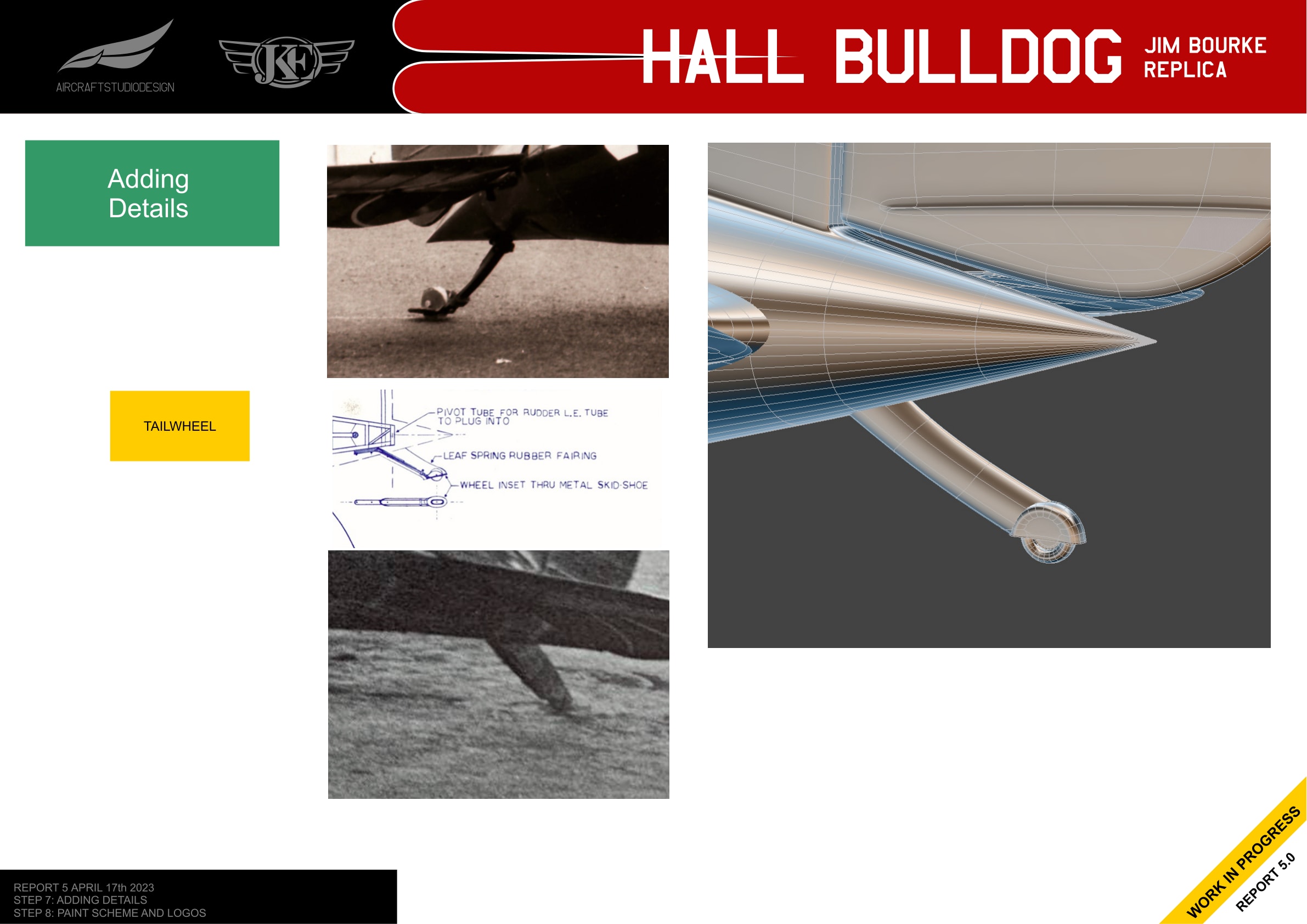
The next phase involved adding all the small details visible in historical photographs. Each detail was modeled by comparing reference photos with the 3D model.
Wing and Fuselage Details
Pitot Tube
Landing Gear Details
Engine Area Details
Fuselage Access Points
Tailwheel
Progressive Refining Methodology
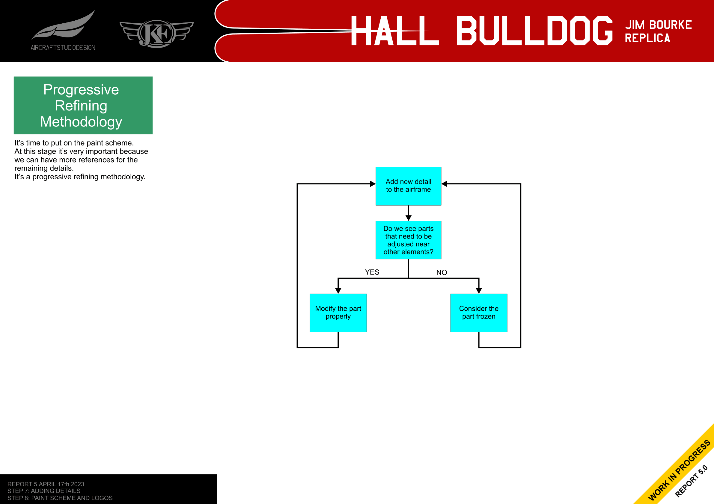
With the paint scheme about to be applied, the team adopted a progressive refining methodology. Adding the paint scheme would reveal more reference points for comparison with photos, allowing further refinement of details.
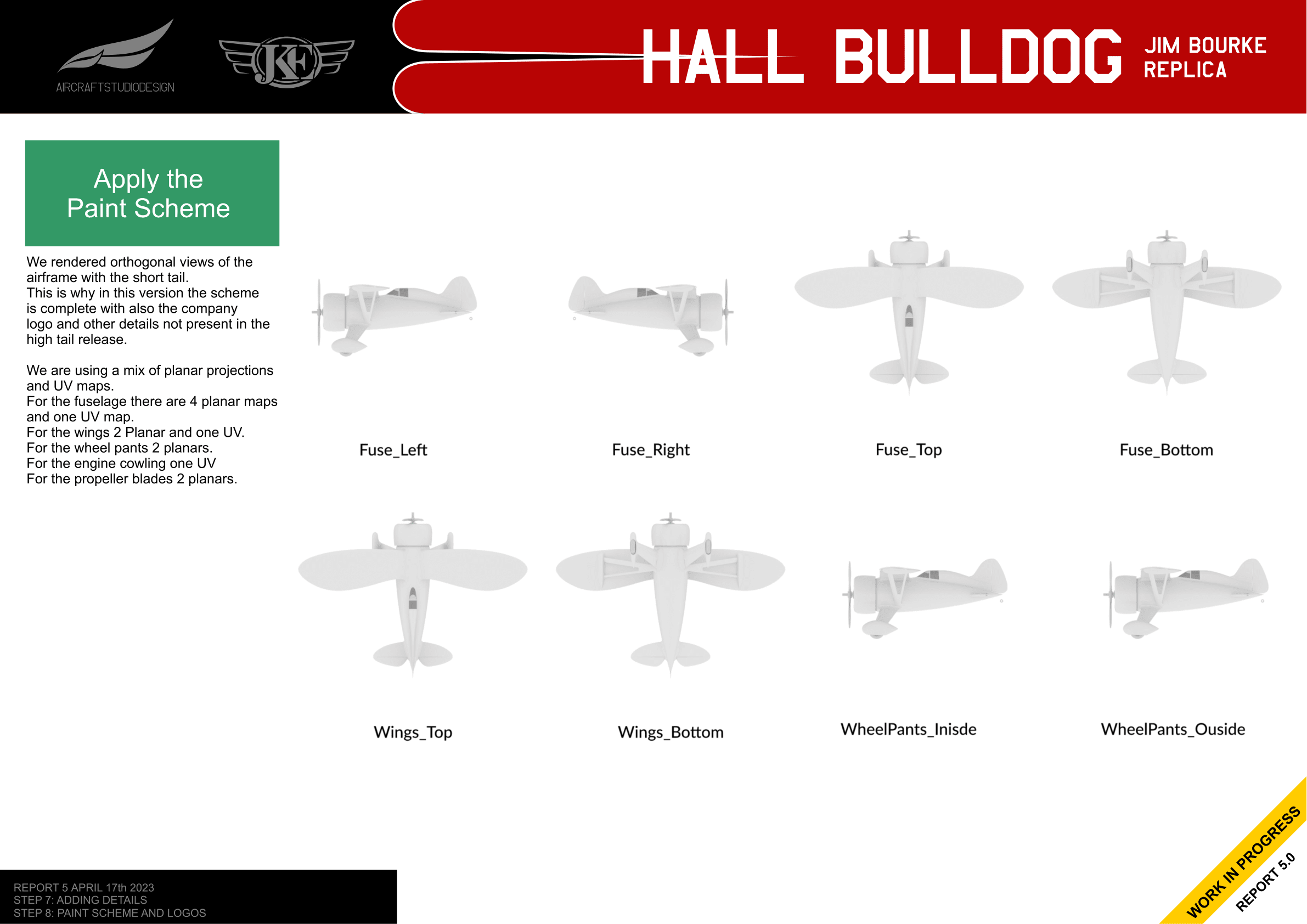
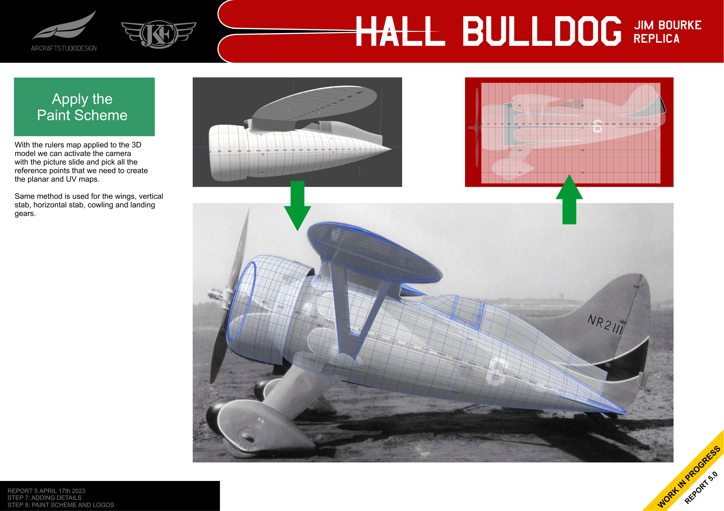
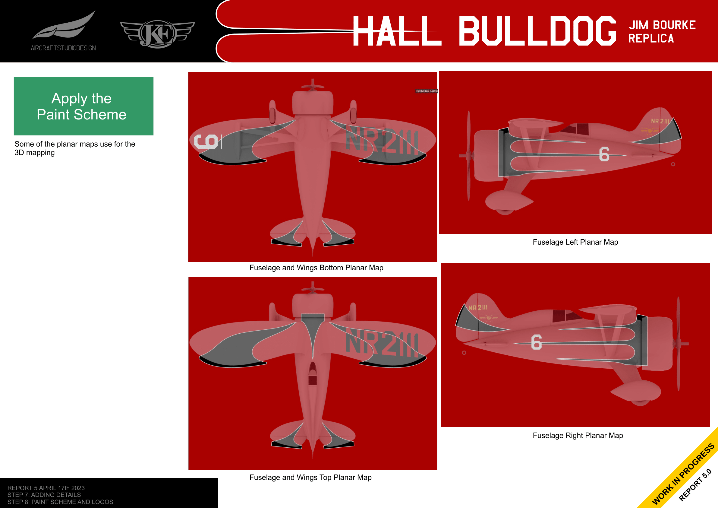
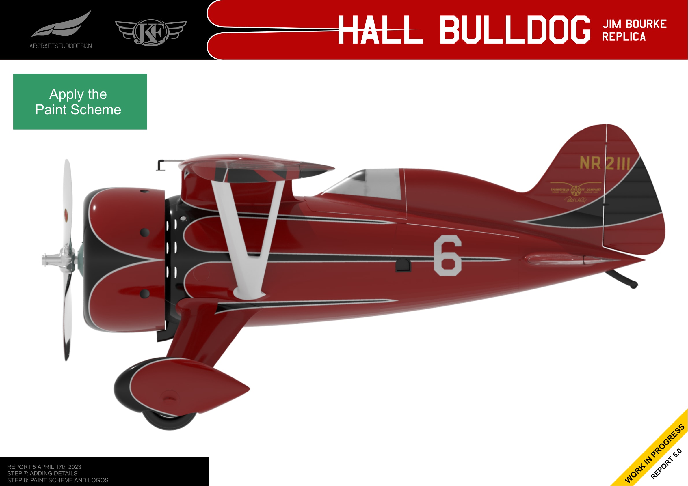
Applying the Paint Scheme
The paint scheme was applied using a combination of planar projections and UV maps. The fuselage required 4 planar maps and one UV map, while the wings used 2 planar maps and one UV map.
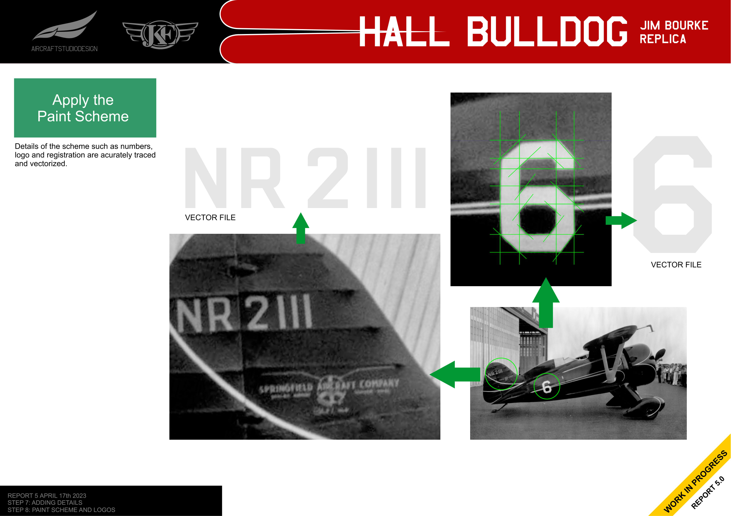
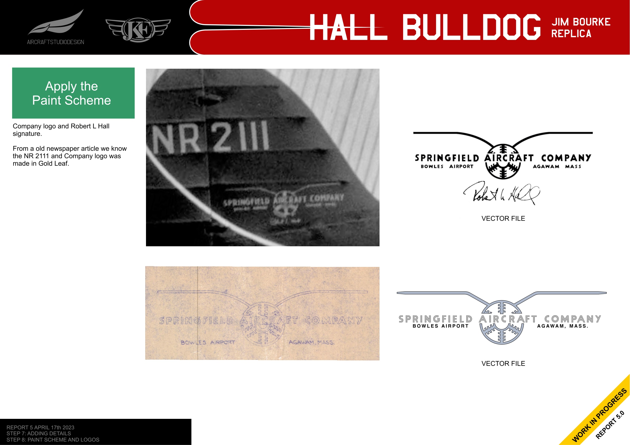
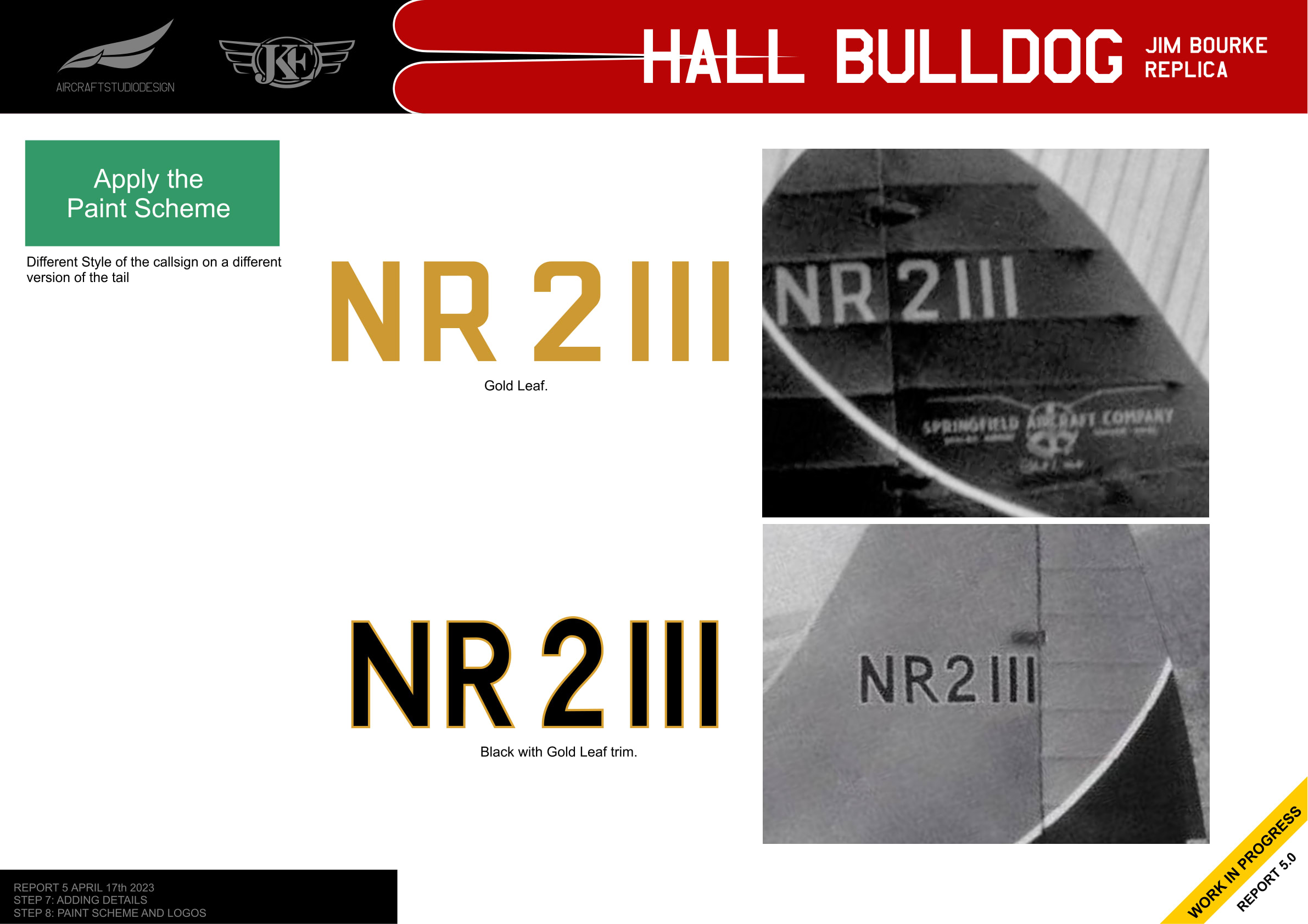
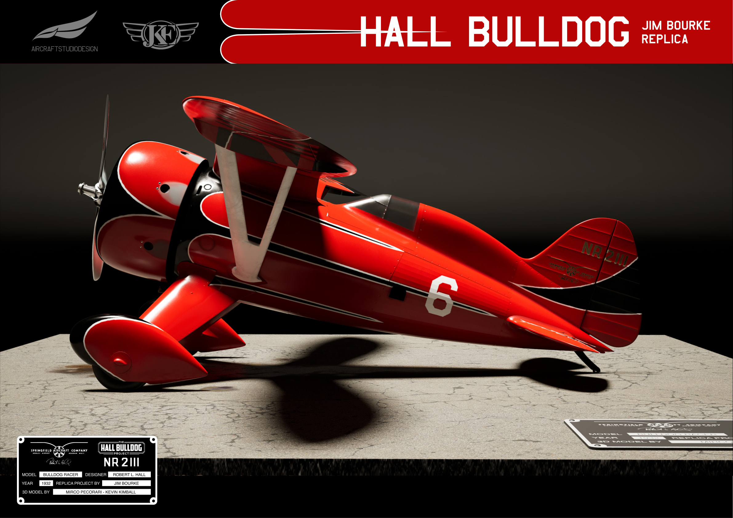
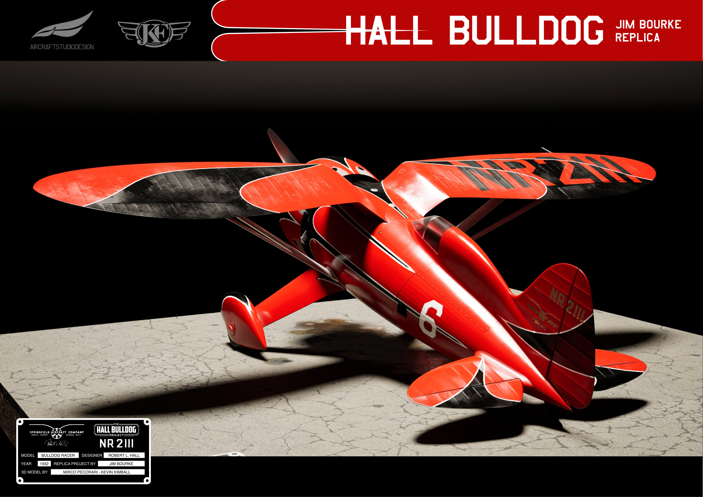
Registration and Race Numbers
Details like the registration number NR 2111, race number 6, and company logos were accurately traced and vectorized from historical photos.
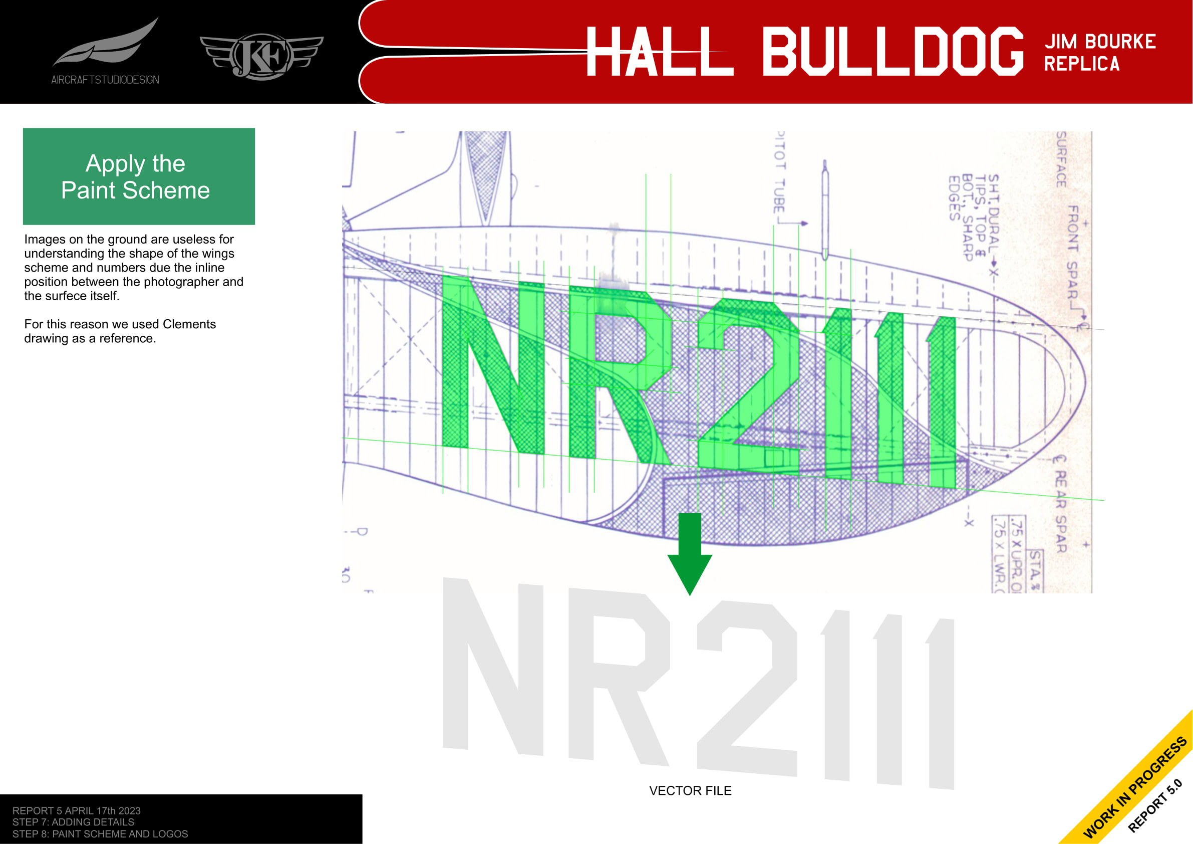
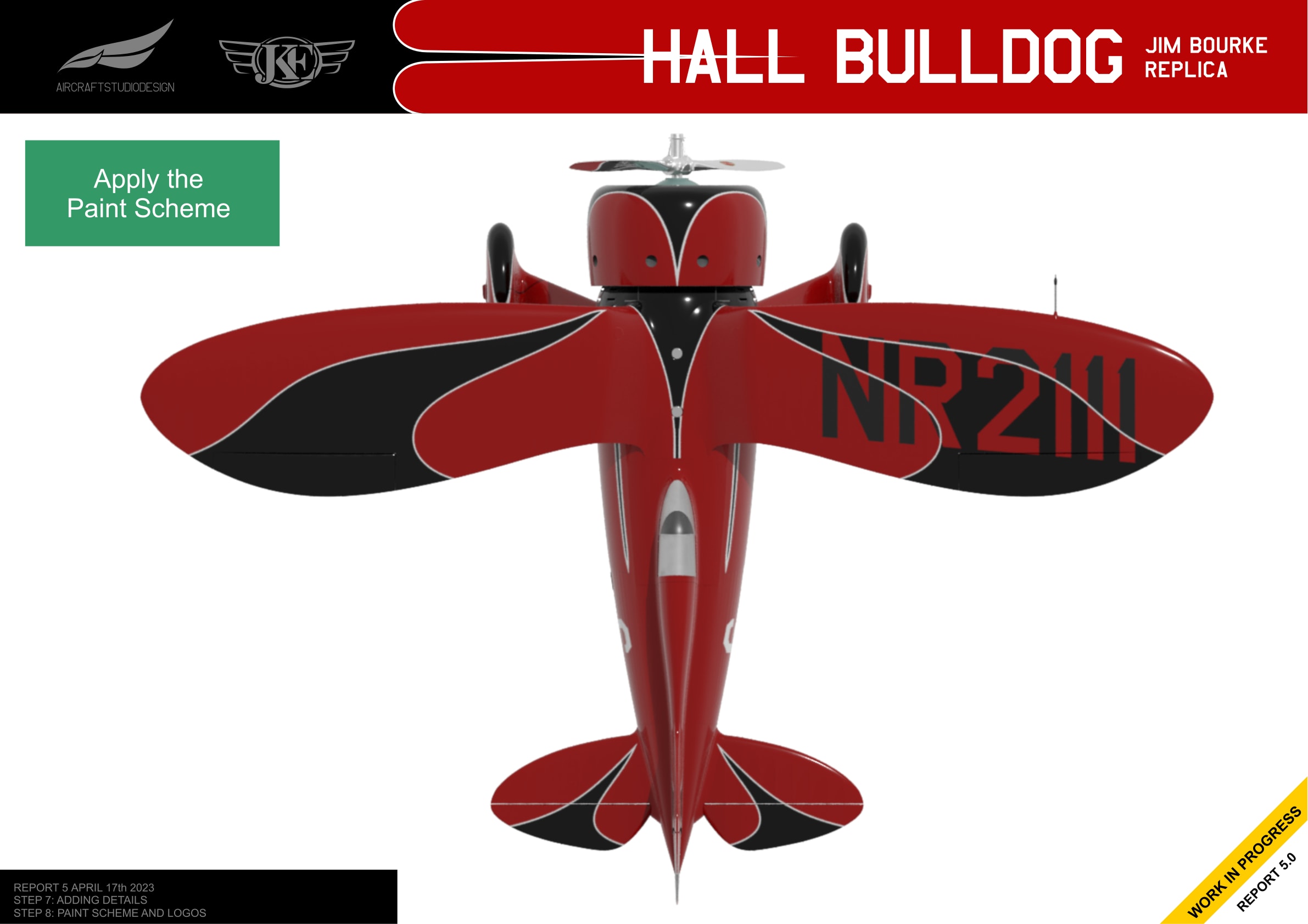
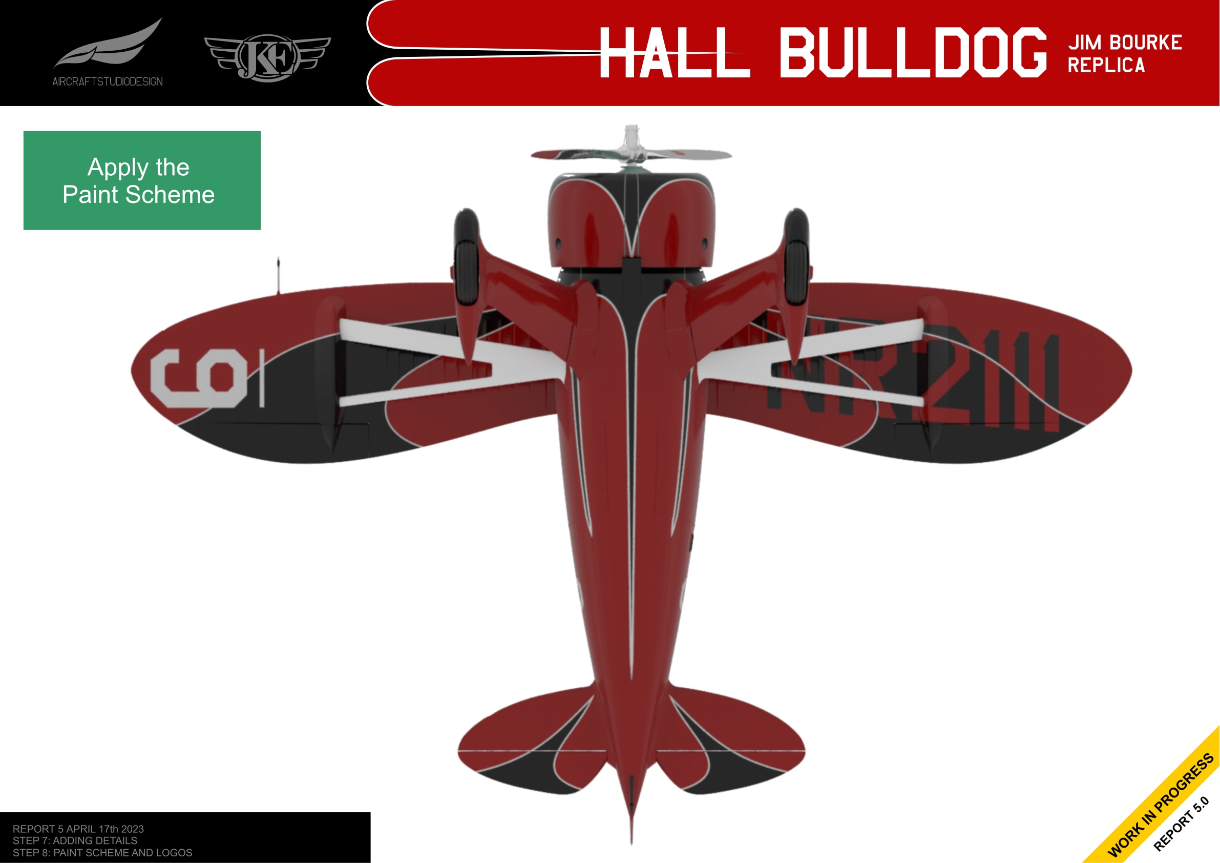
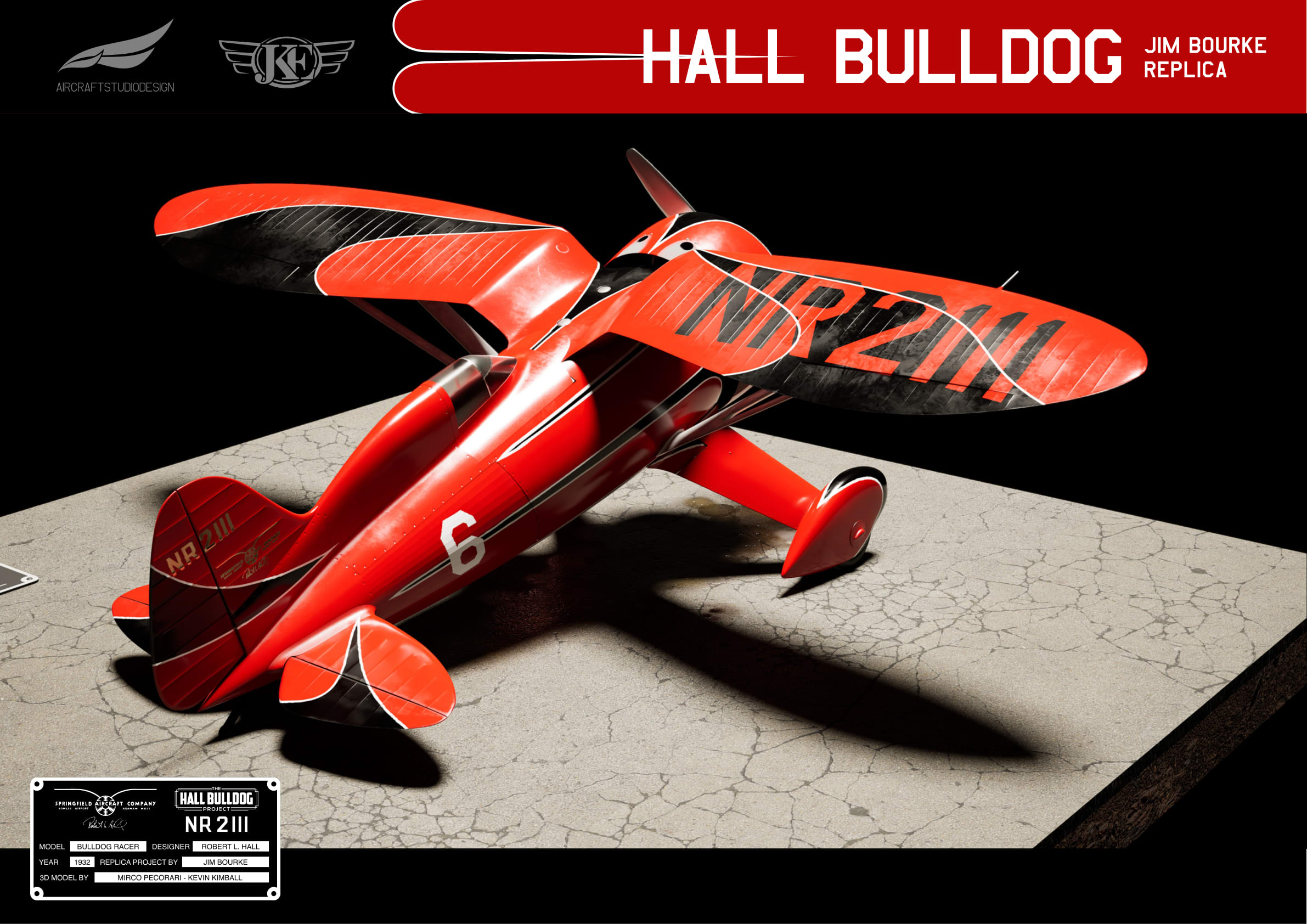
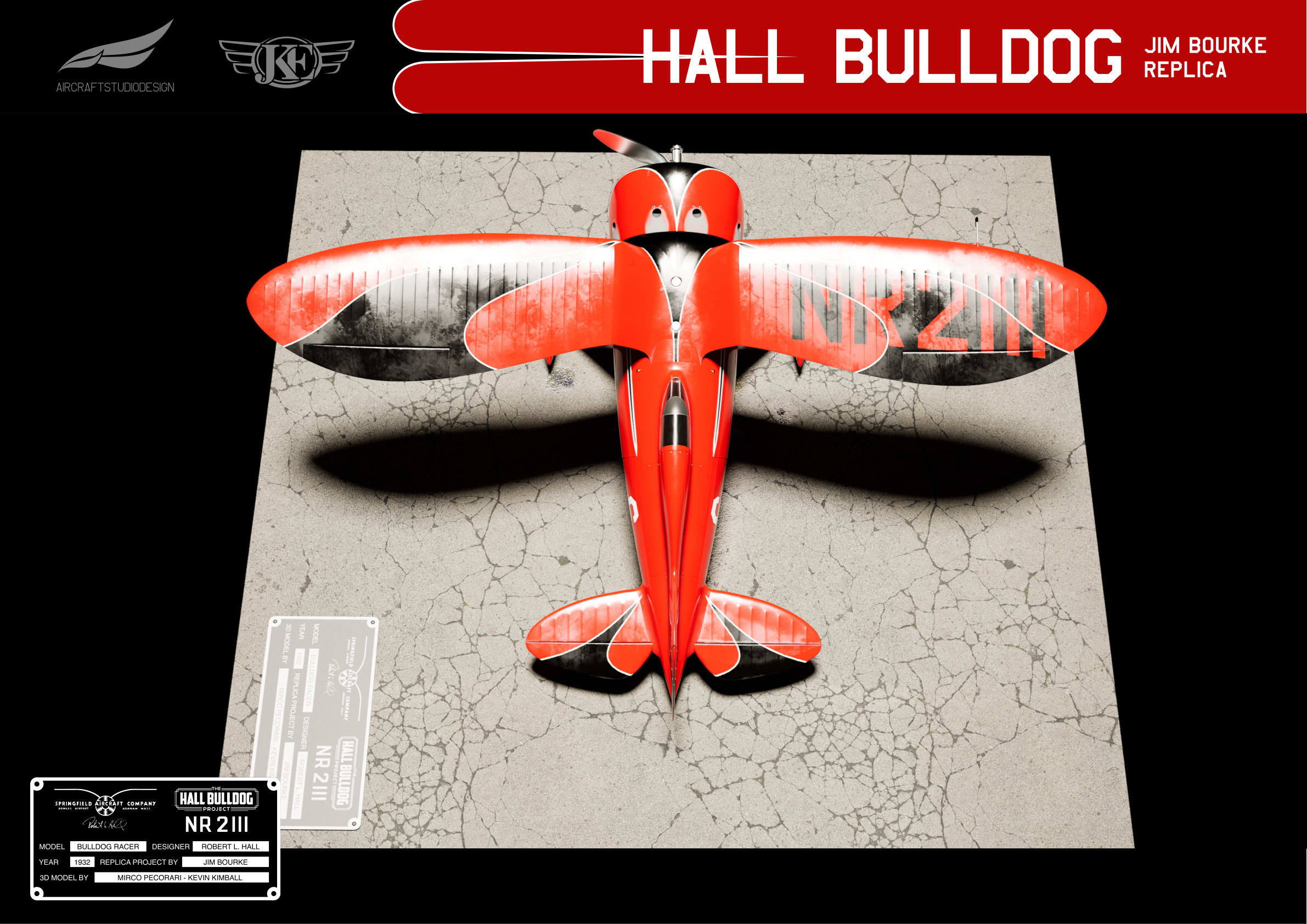
Wing Markings
Ground images were not useful for understanding the wing registration due to the camera angle. The Clements drawing was used as a reference instead.
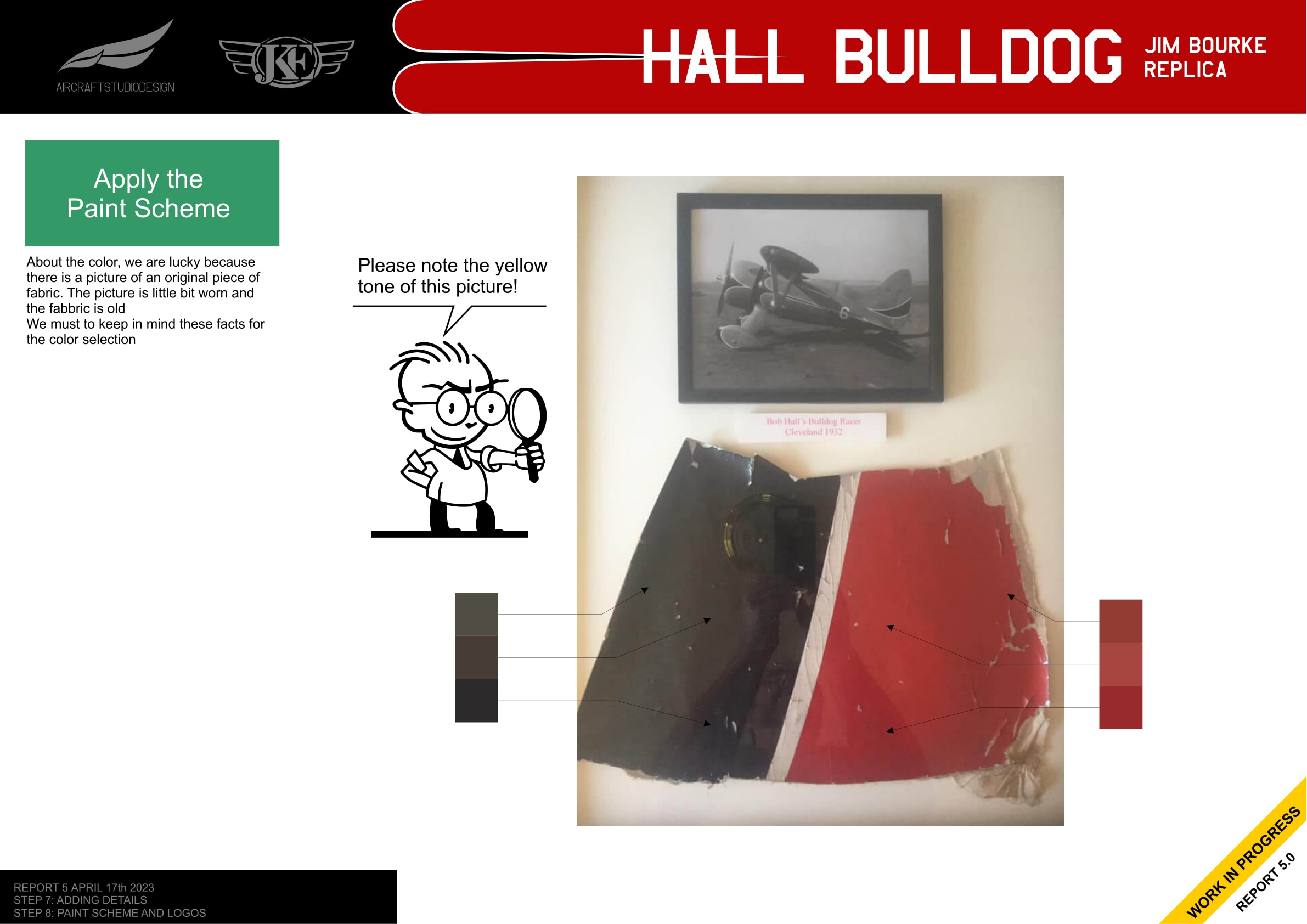
Color Matching
The team was fortunate to have access to an original piece of fabric from the aircraft. Despite the yellowing of the photo and aging of the fabric, this provided an invaluable reference for the color selection.
Complete Paint Scheme
Final Result with Weathering
The team felt something was missing from the clean renders. The surface of the plane was too smooth for a tube and fabric aircraft built with hammer and welder—a wild racing machine from the golden age of aviation with pilots and mechanics with greasy hands and mud on their shoes.
In the spirit of creating a credible replica, weathering was added using Substance Painter and Unreal 5.1 for rendering. The weathering includes metal bumps, rivets, and oil stains.
Project Summary
Over the course of nearly a year (June 2022 - May 2023), Aircraft Studio Design created an accurate 3D model of the 1932 Hall Bulldog racing aircraft to support Jim Bourke’s goal of building a full-scale flying replica.
The project confirmed several important specifications, which align with information from Bob Hall’s correspondence with Vern Clements:
- Wingspan: 7.9248m (26 ft)
- Cowling maximum diameter: 1.33m
- Gull wing configuration with characteristic dihedral
- Three versions of the vertical stabilizer/rudder documented
Related Reports
- Report 1: Pictures Analysis and 2D Views - Initial analysis and 2D drawings
- Report 3: Building and Validating the Model - 3D modeling and photo comparison
- Report 4: Refined Details - CAD integration and empennage modeling
