Hall Bulldog 3D Modeling: Refined Details

Part of The Hall Bulldog Project — documenting Bob Hall's 1932 Thompson Trophy racer.
Explore the Project →This is the fourth report from Mirco Pecorari of Aircraft Studio Design, documenting continued refinement of the Hall Bulldog 3D model. This report covers the integration of Kevin Kimball’s CAD engineering model with Mirco’s 3D skin model, plus detailed modeling of the vertical and horizontal stabilizers.
Matching CAD Engineering with the 3D Model
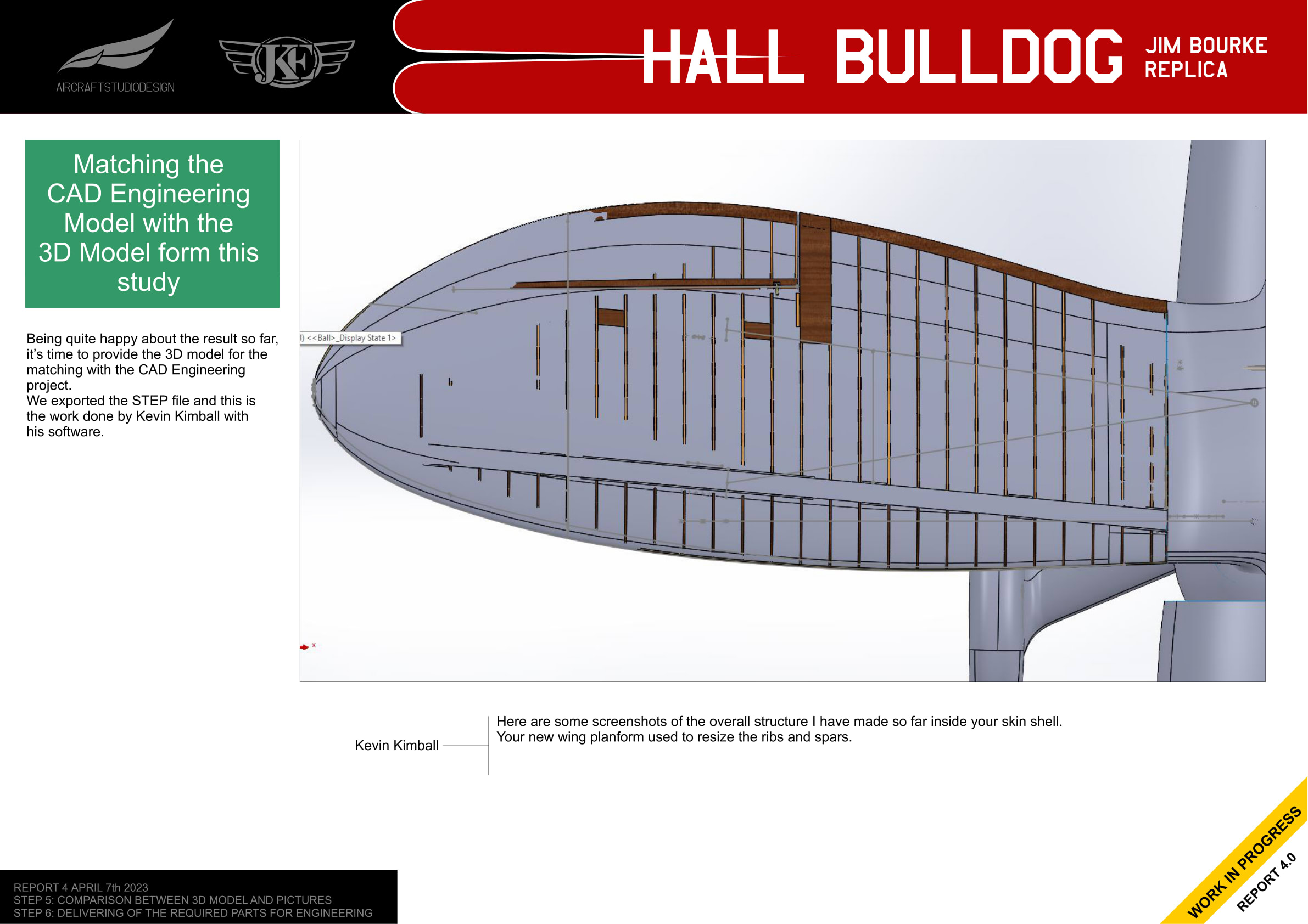
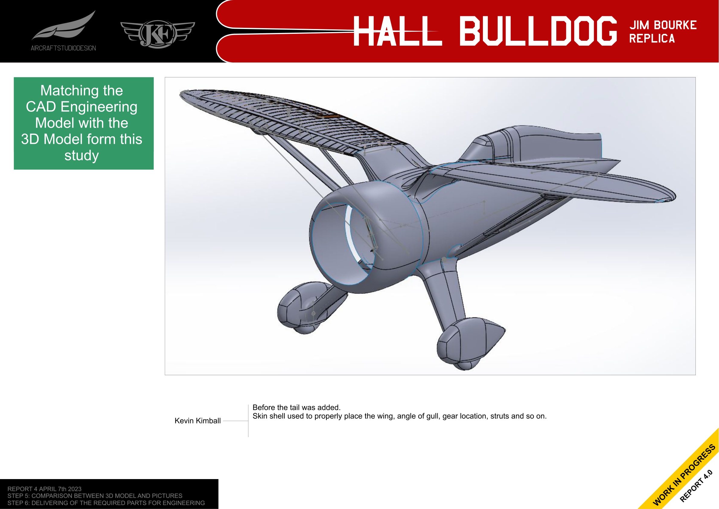
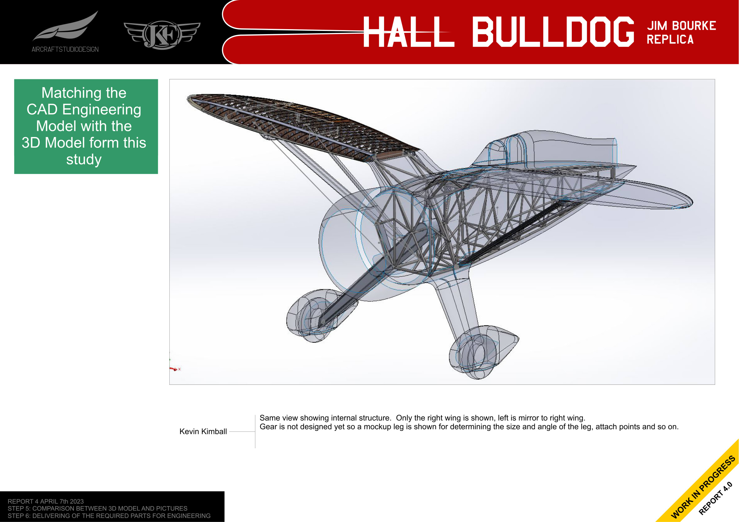
With the external 3D model validated against historical photos, the next step was integrating it with Kevin Kimball’s CAD engineering model. The STEP file was exported and Kevin provided screenshots showing how the internal tube structure fits within the skin shell.
Wing Planform Refinement
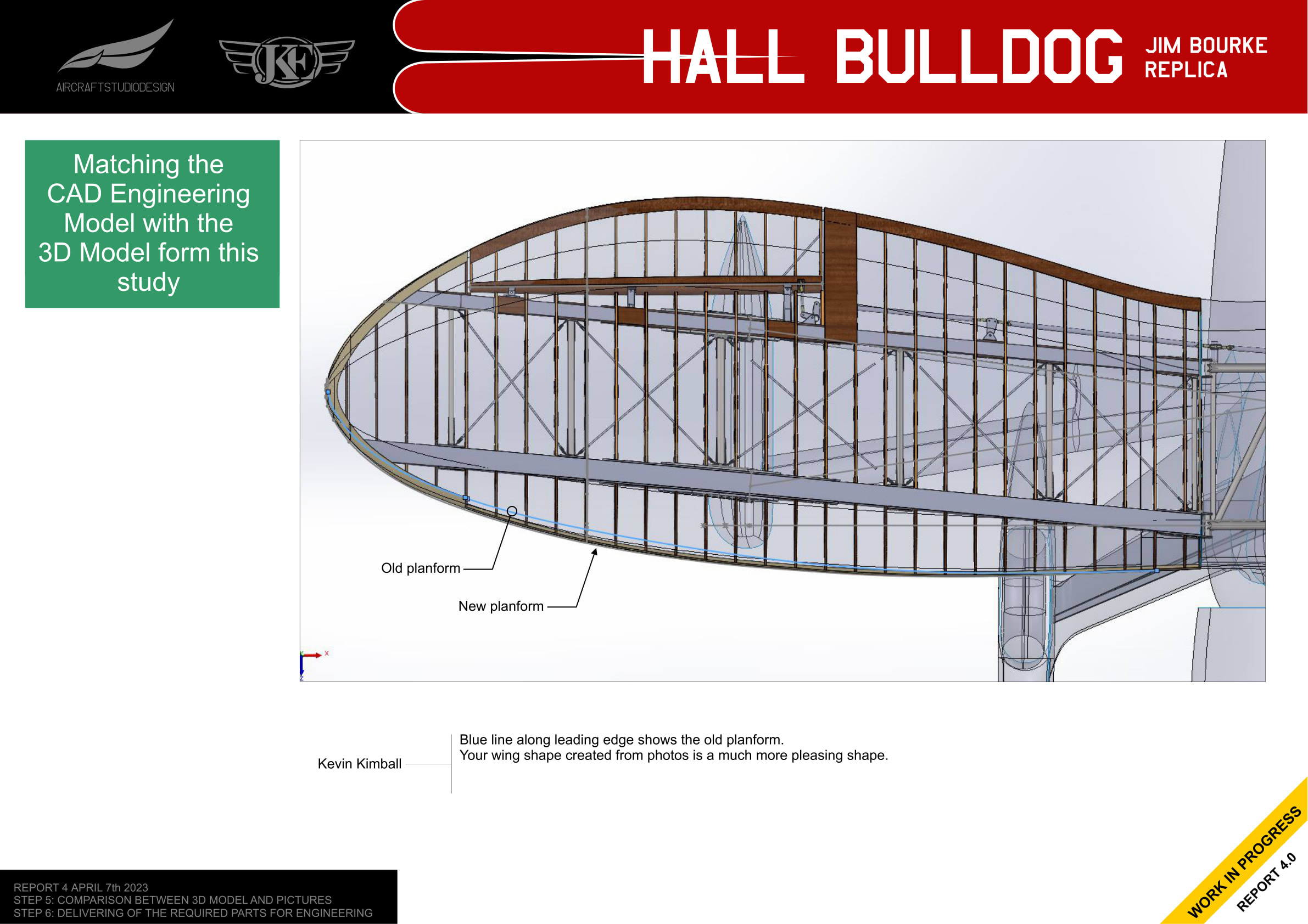
Kevin noted that the wing shape created from photos was “a much more pleasing shape” than the original. The blue line shows the old planform along the leading edge, while the new shape better matches the historical photographs.
Gull Wing Attachment Details
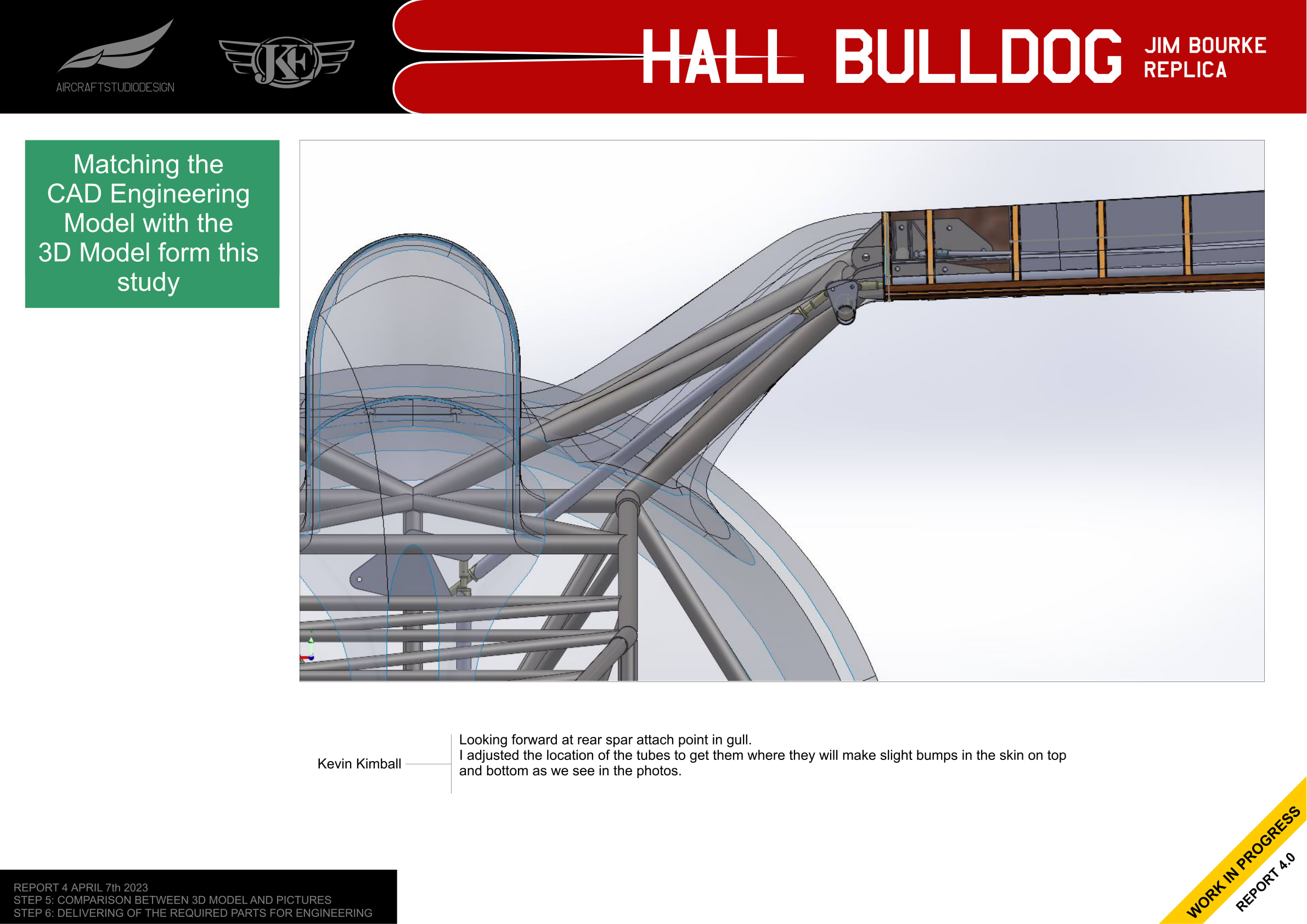
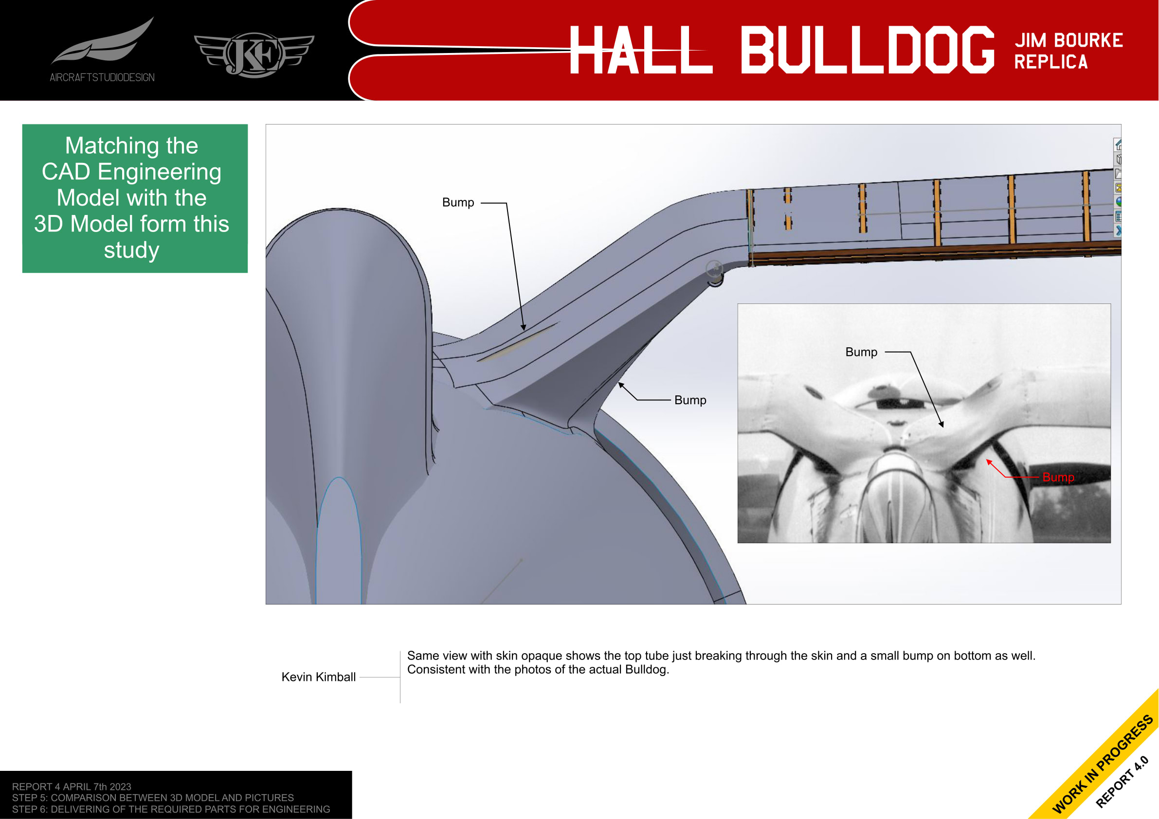
The rear spar attachment point in the gull section required careful positioning. Kevin adjusted the location of the tubes to create the slight bumps visible in the skin on top and bottom—exactly as seen in photos of the actual Bulldog.
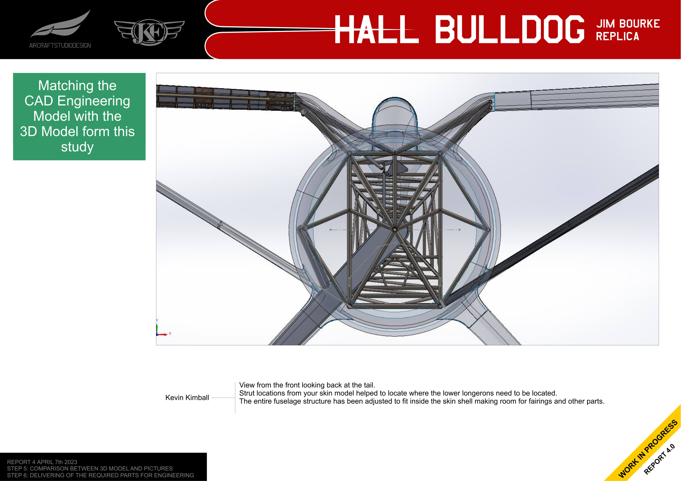
Internal Structure Views
Kevin’s engineering model shows the complete fuselage structure adjusted to fit inside the skin shell while making room for fairings and other parts.
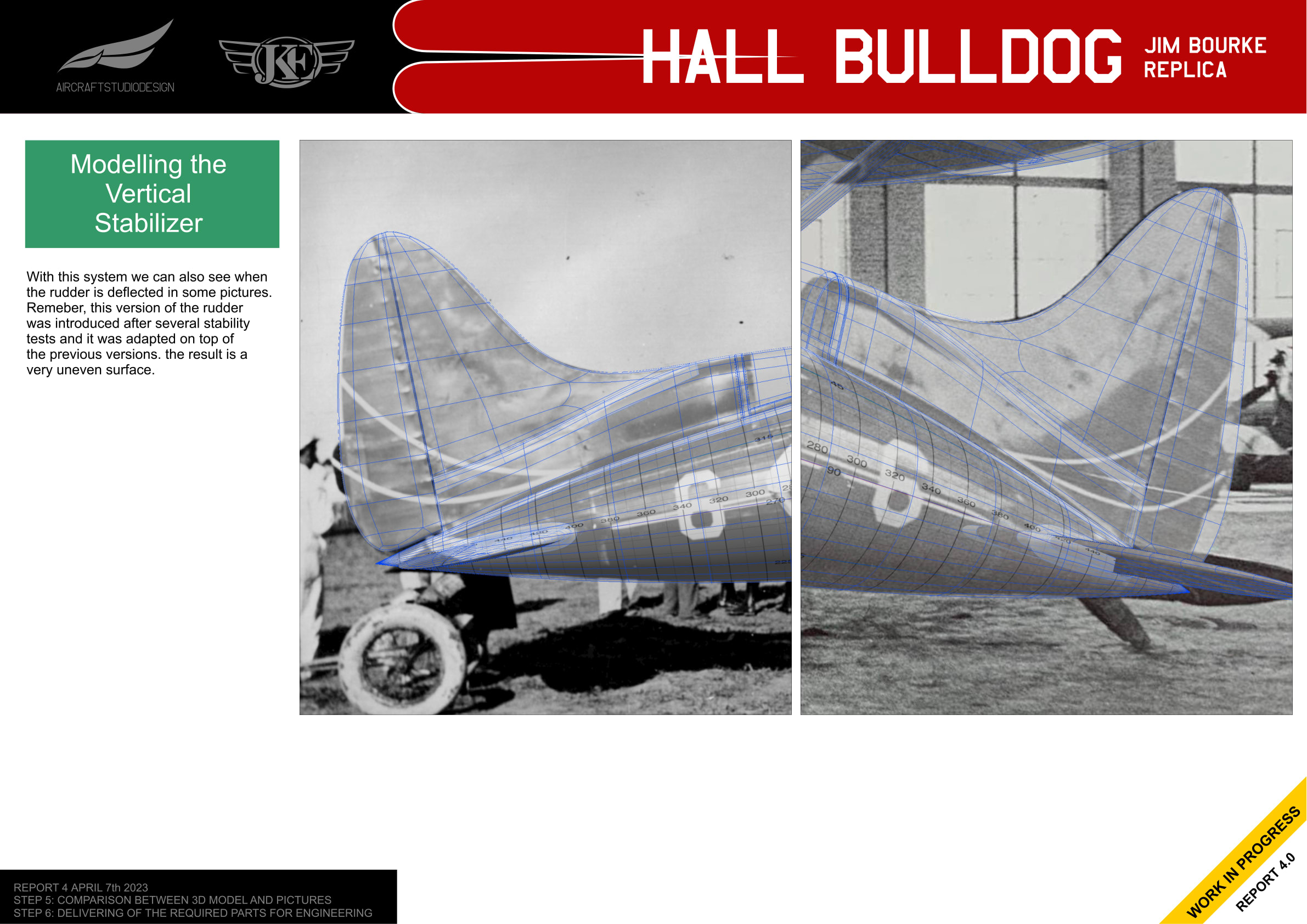
Modeling the Vertical Stabilizer
With a validated 3D model base that matches the photo collection, the vertical stabilizer and rudder could be modeled directly from photos as shape and dimension references.
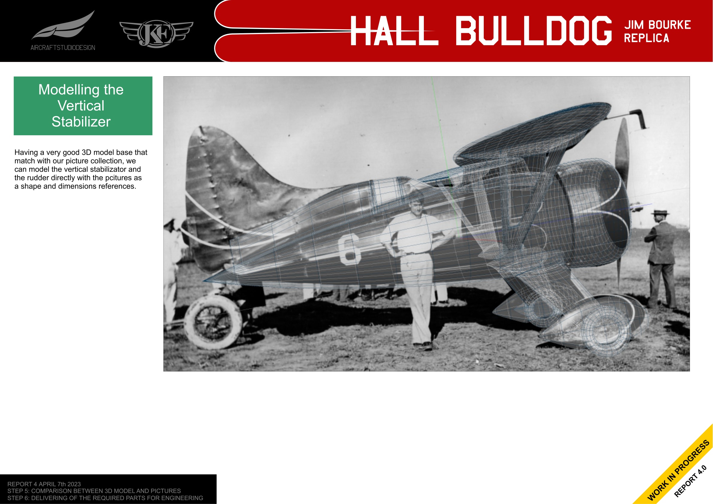
The overlay method also reveals when the rudder is deflected in photos. The extended rudder version was introduced after stability tests and was adapted on top of the previous version, resulting in a somewhat uneven surface.
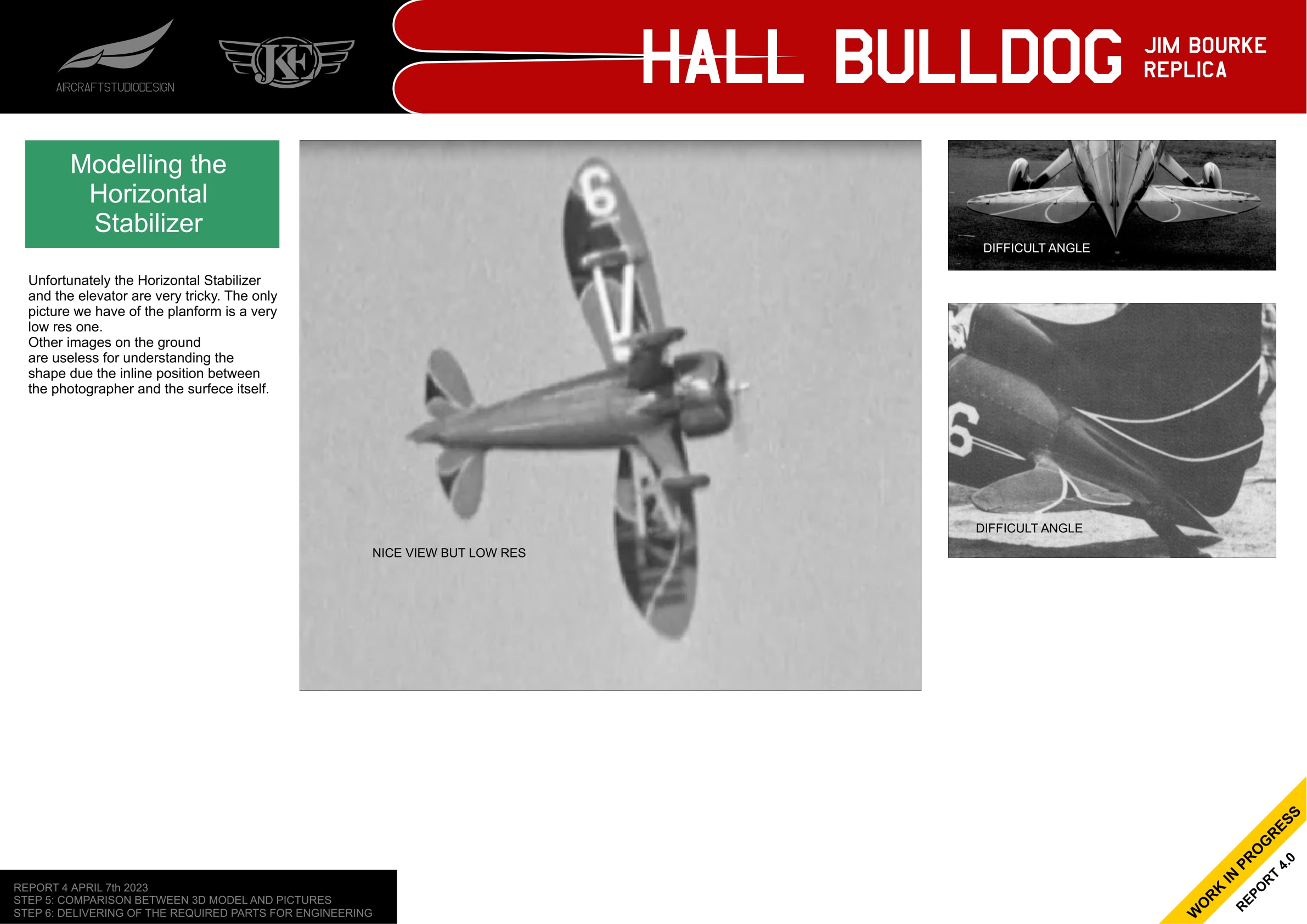
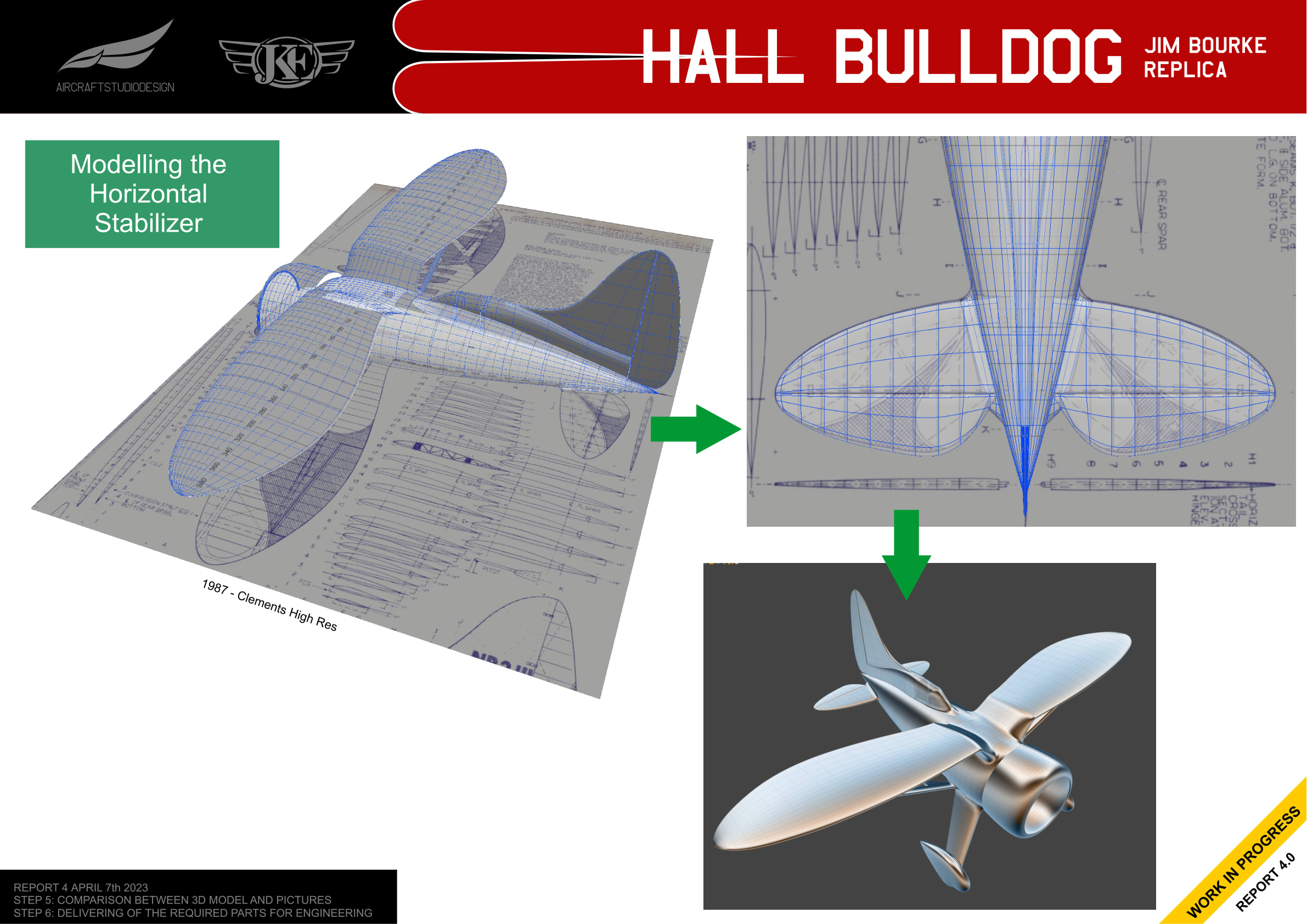
Modeling the Horizontal Stabilizer
The horizontal stabilizer and elevator presented unique challenges. The only available photo showing the planform clearly is very low resolution. Other ground images are useless for understanding the shape due to the viewing angle between the photographer and the surface.
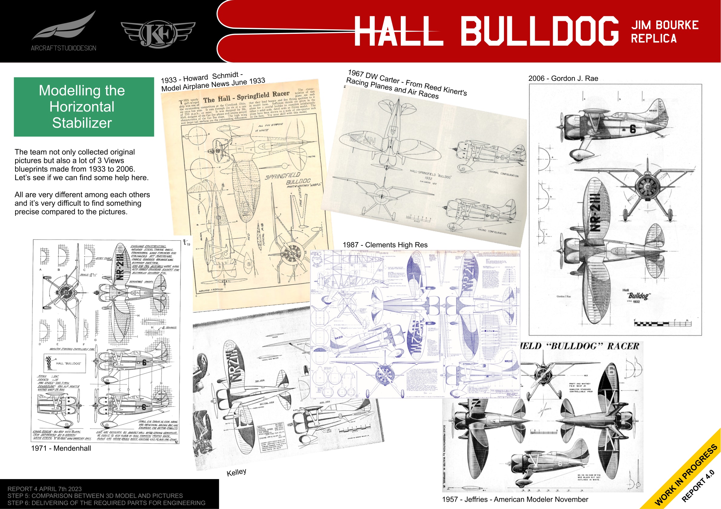
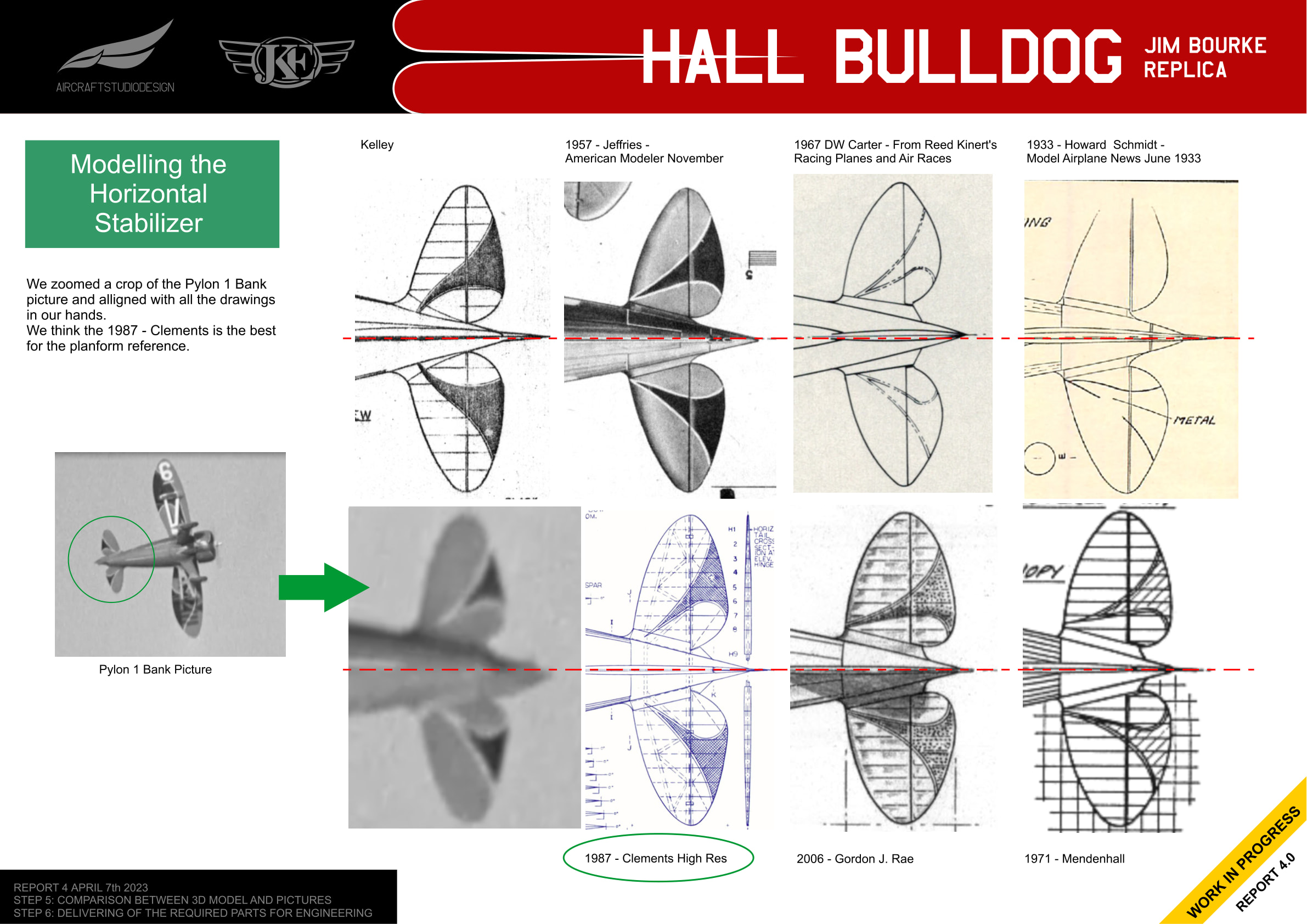
Comparing Historical Drawings
The team collected not only original pictures but also 3-views blueprints made from 1933 to 2006. These drawings vary significantly from each other, making it difficult to find something that precisely matches the photos.
By zooming in on the Pylon 1 bank picture and comparing it with all the drawings, the team determined that the 1987 Clements drawing is the best reference for the horizontal stabilizer planform.
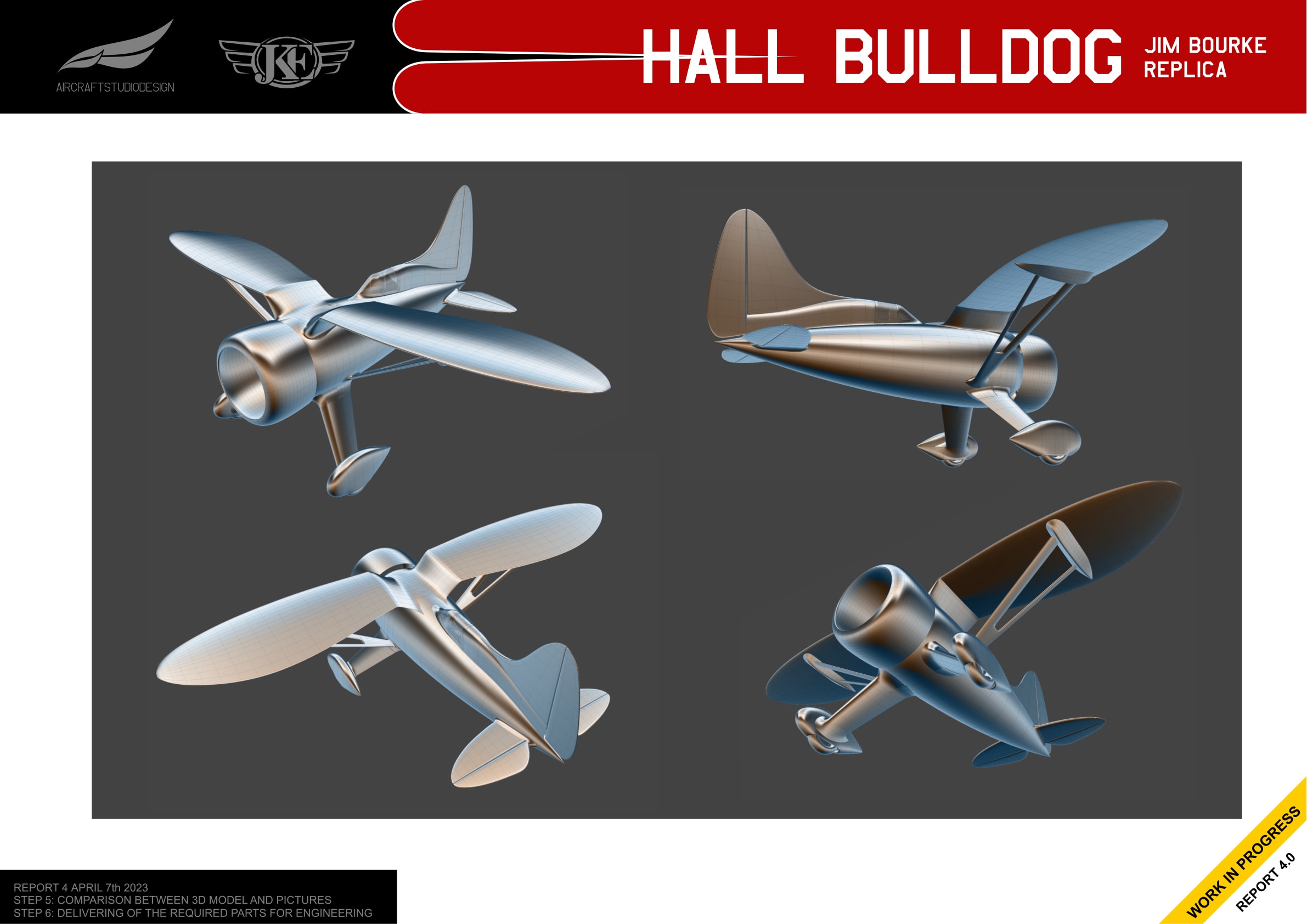
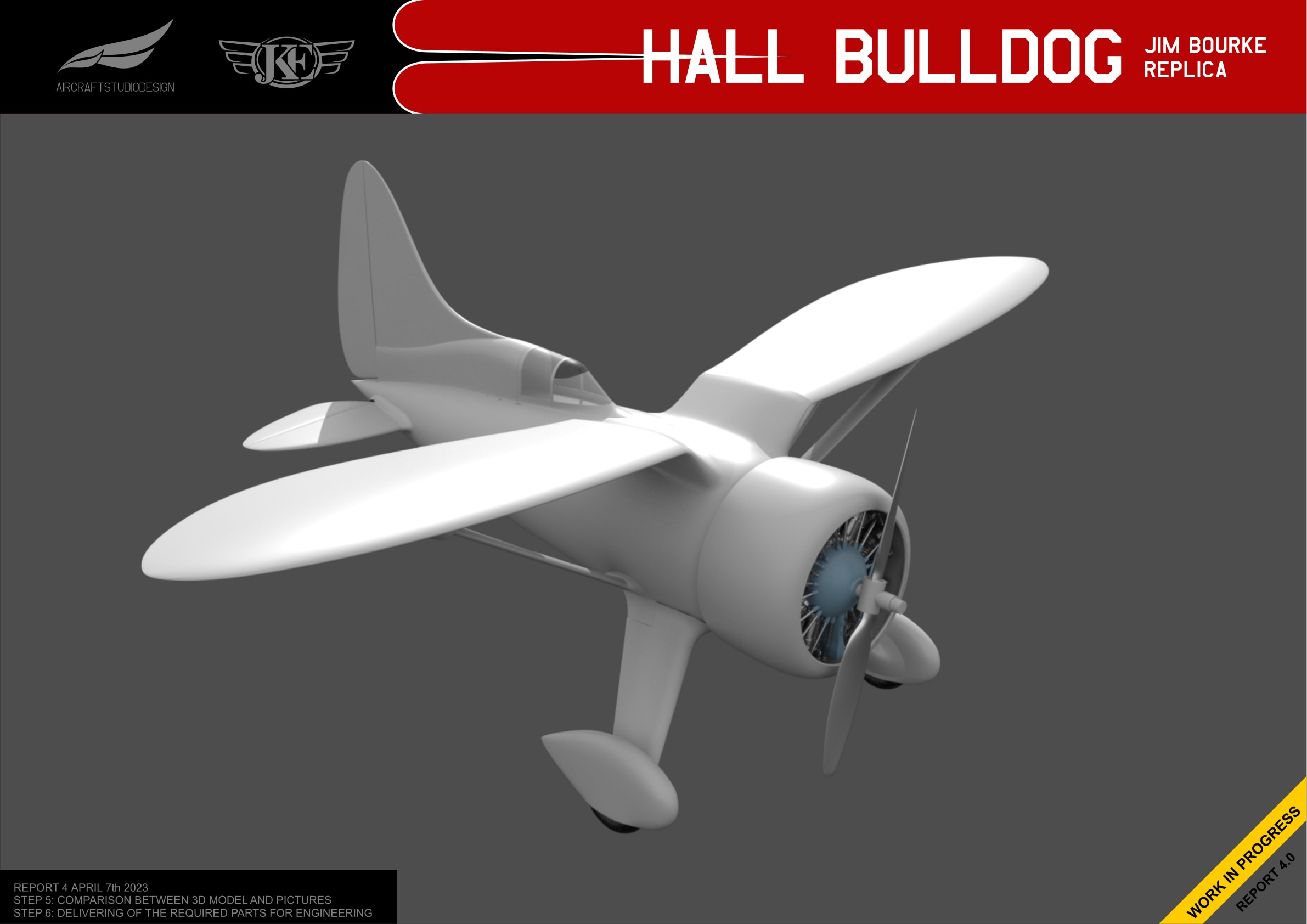
Current 3D Model Status
With the empennage complete, the model now shows the full aircraft from multiple angles.
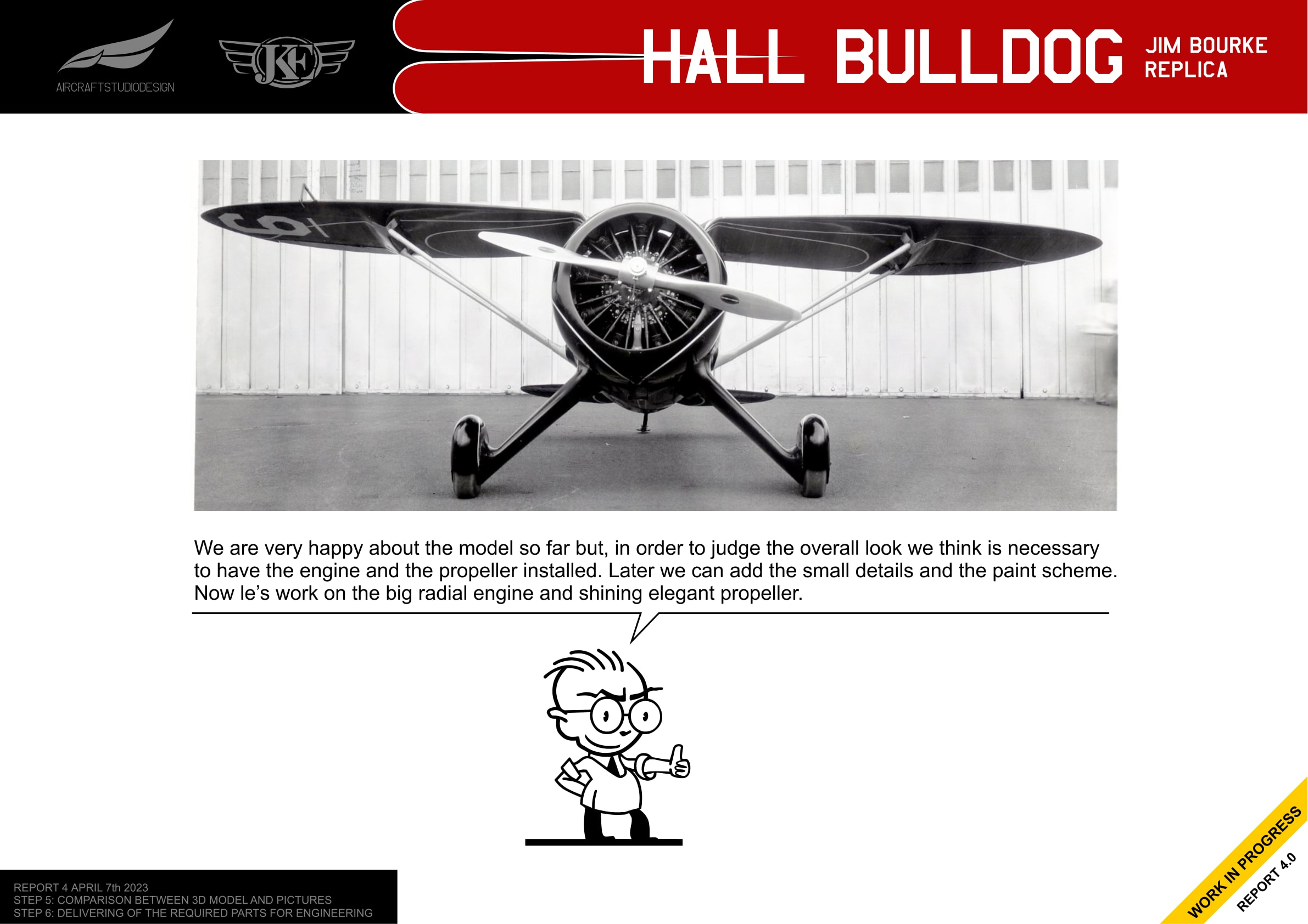
Adding the Engine and Propeller
The team was happy with the model so far, but to judge the overall look it was necessary to have the engine and propeller installed. This would allow adding small details and the paint scheme later.
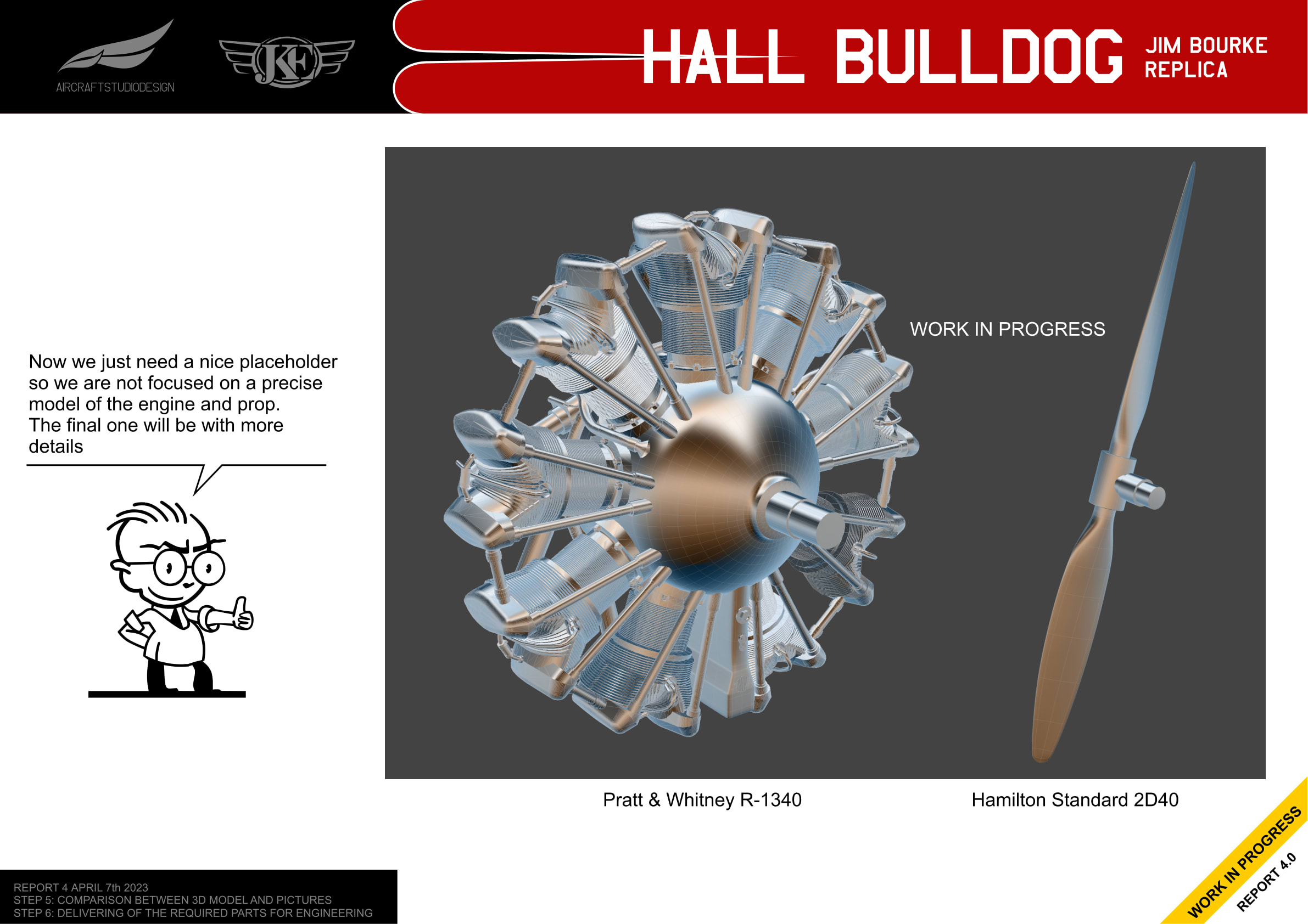
For now, placeholder models were created for the Pratt & Whitney R-1340 radial engine and Hamilton Standard 2D40 propeller. The final versions will include more detail.
Related Reports
- Report 1: Pictures Analysis and 2D Views - Initial analysis and 2D drawings
- Report 3: Building and Validating the Model - 3D modeling and photo comparison
- Report 5: Final Report - Comprehensive final documentation
