Hall Bulldog 3D Modeling: Pictures Analysis and 2D Views

Part of The Hall Bulldog Project — documenting Bob Hall's 1932 Thompson Trophy racer.
Explore the Project →This is the first report from Mirco Pecorari of Aircraft Studio Design, documenting the process of creating an accurate 3D model of the Hall Bulldog for a full-scale replica.
The Design Process
Mirco’s approach follows a systematic 6-step process:
- Pictures and Drawings Analysis - Collecting and analyzing historical photos and drawings
- Pictures Matching and Perspective Understanding - Finding vanishing points, identifying distortion-free areas
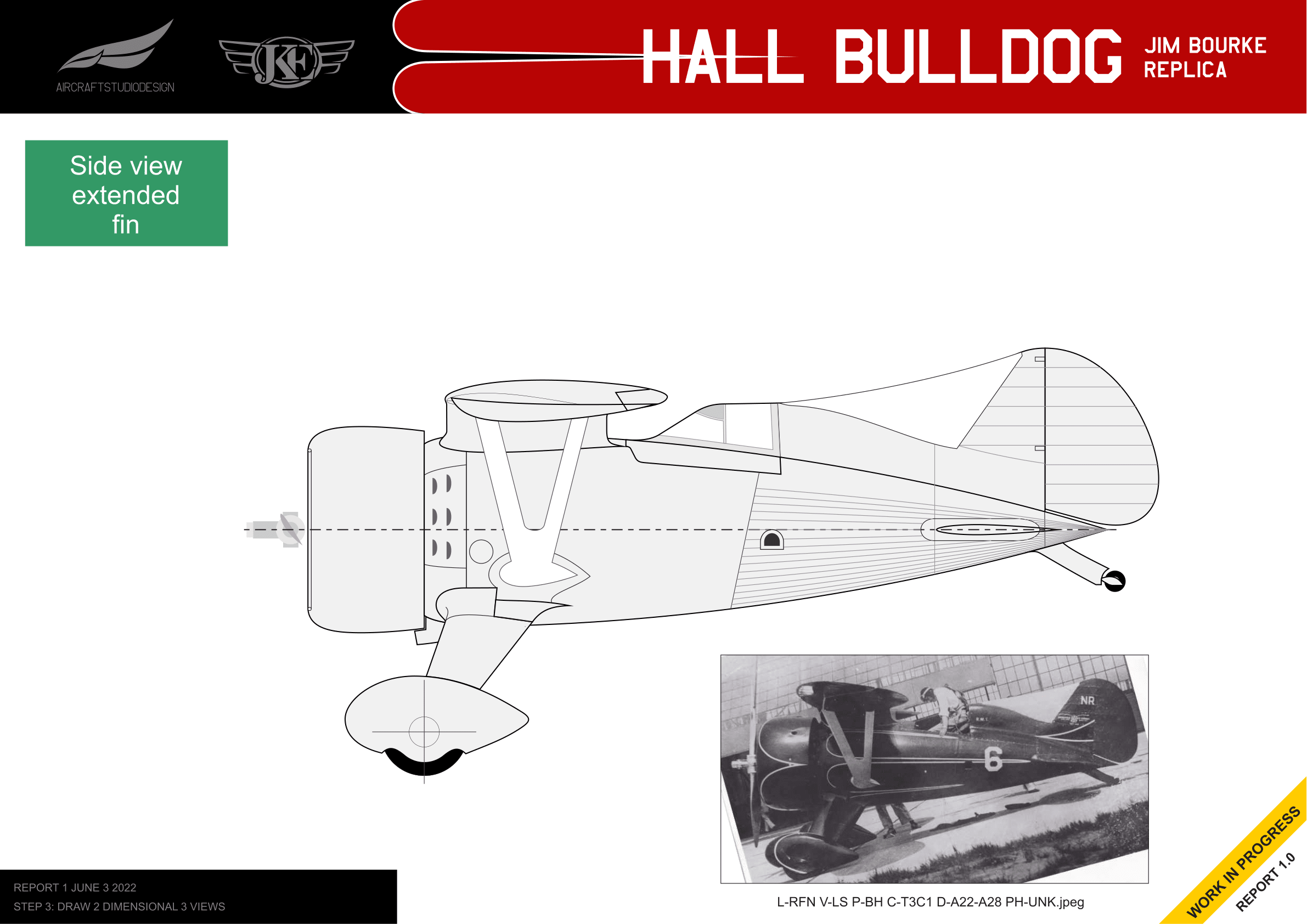
- Draw 2 Dimensional 3 Views - Creating accurate 2D side/top/front views
- 3D Modeling Based on 2D 3 Views - Building the 3D model
- Comparison Between 3D Model and Pictures - Validating accuracy
- Delivery of Required Parts for Engineering - Exporting for mechanical engineering
This report covers Steps 1-3, completed as of June 2022.
The Challenge
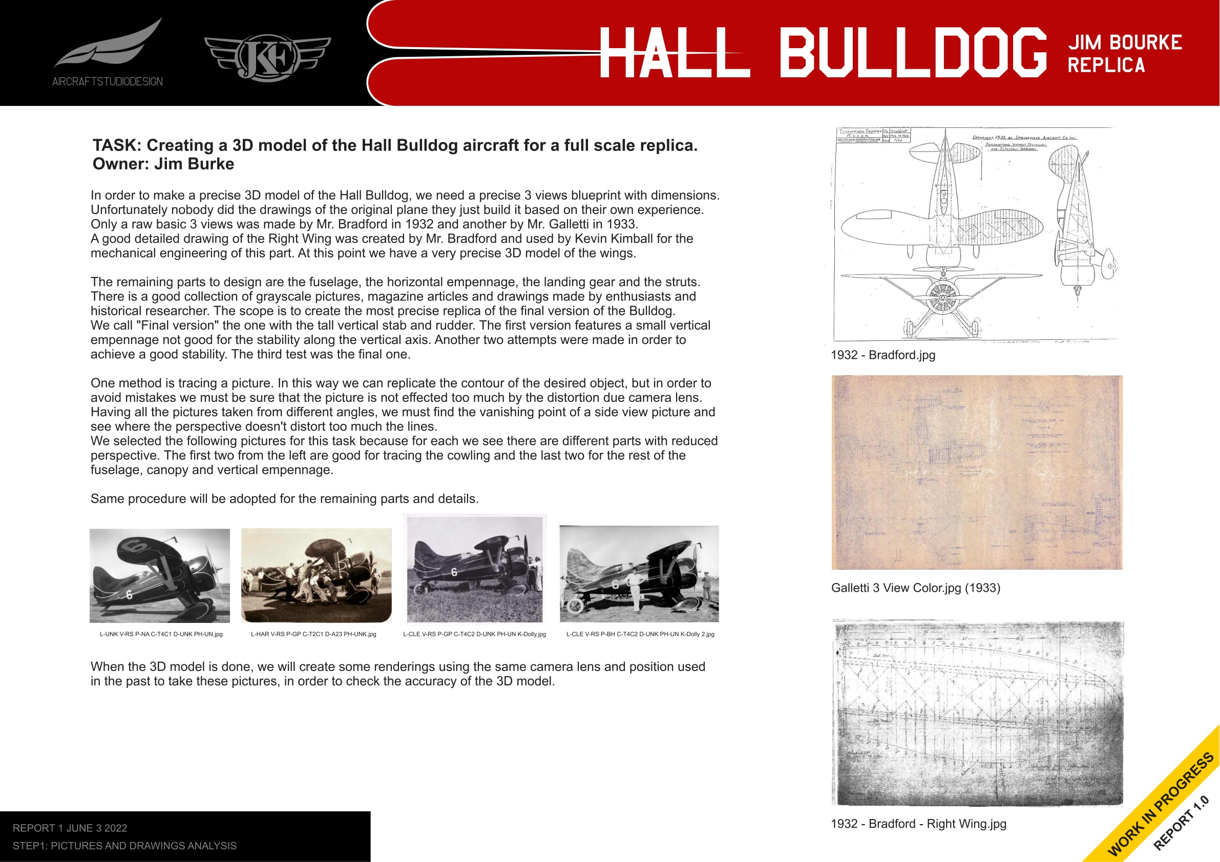
Creating a precise 3D model of the Hall Bulldog requires accurate blueprints with dimensions, but unfortunately no complete drawings of the original plane exist. Only basic 3-views drawings were made by Mr. Bradford in 1932 and Mr. Galletti in 1933. A detailed drawing of the right wing was created by Mr. Bradford and used by Kevin Kimball for the wing model.
The remaining parts to design include the fuselage, horizontal empennage, landing gear, and struts. The goal is to create the most precise replica of the final version of the Bulldog—the one with the tall vertical stabilizer and rudder.
Step 2: Picture Tracing Method
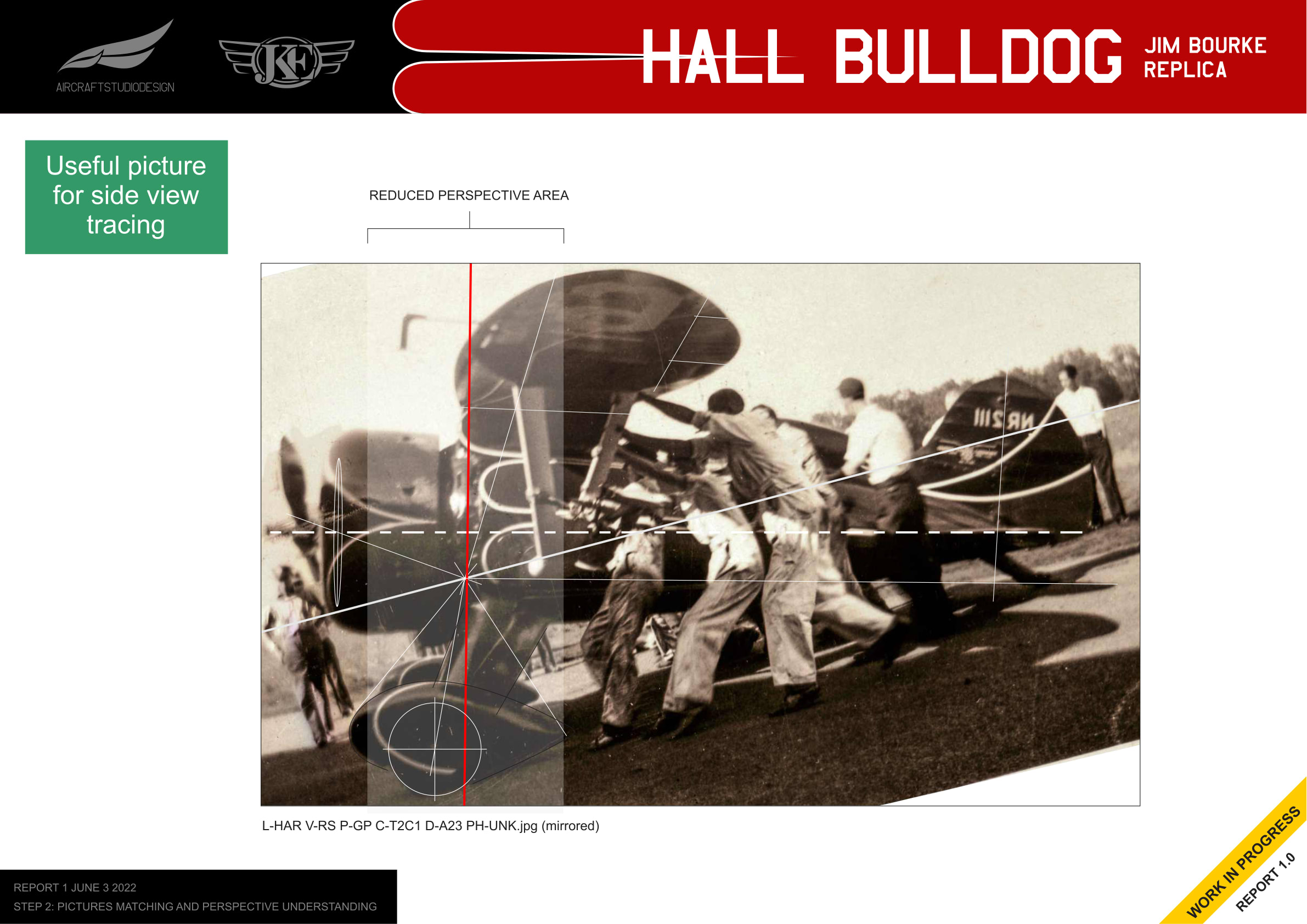
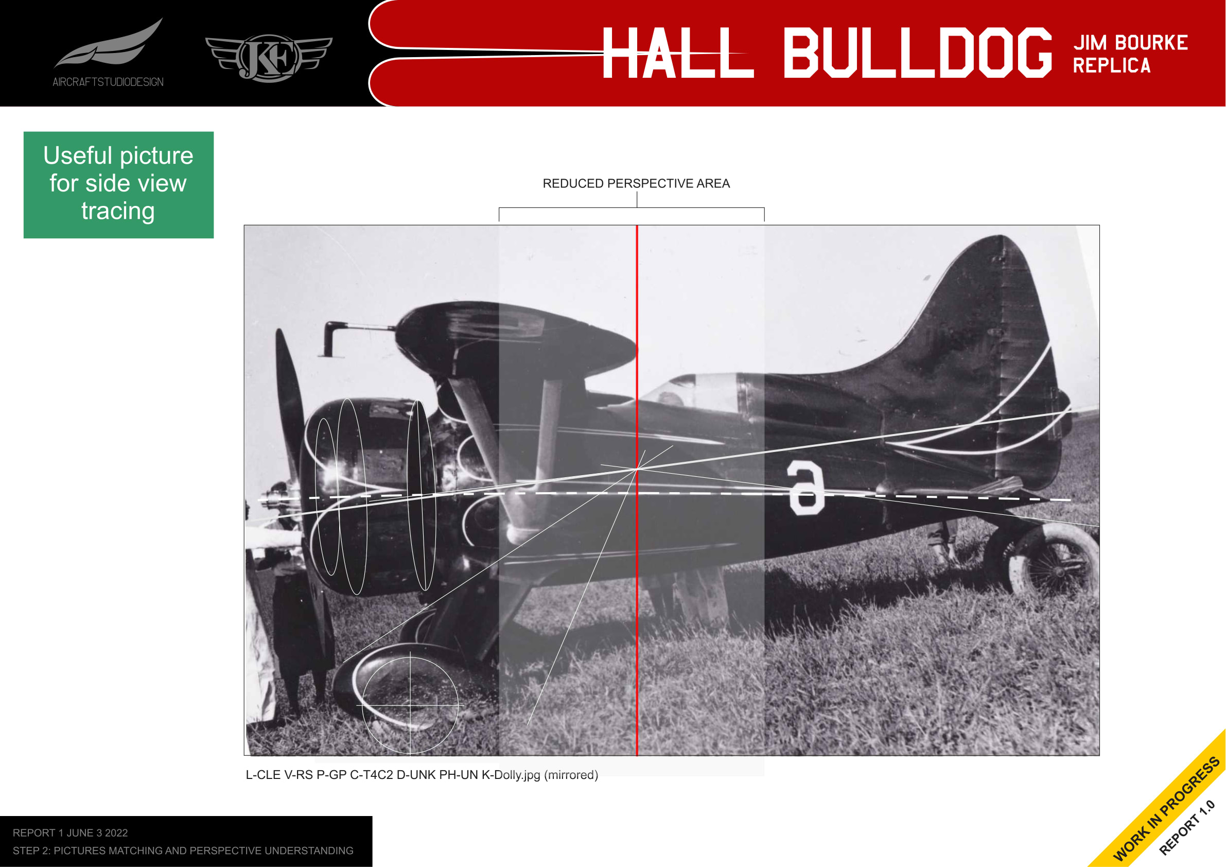
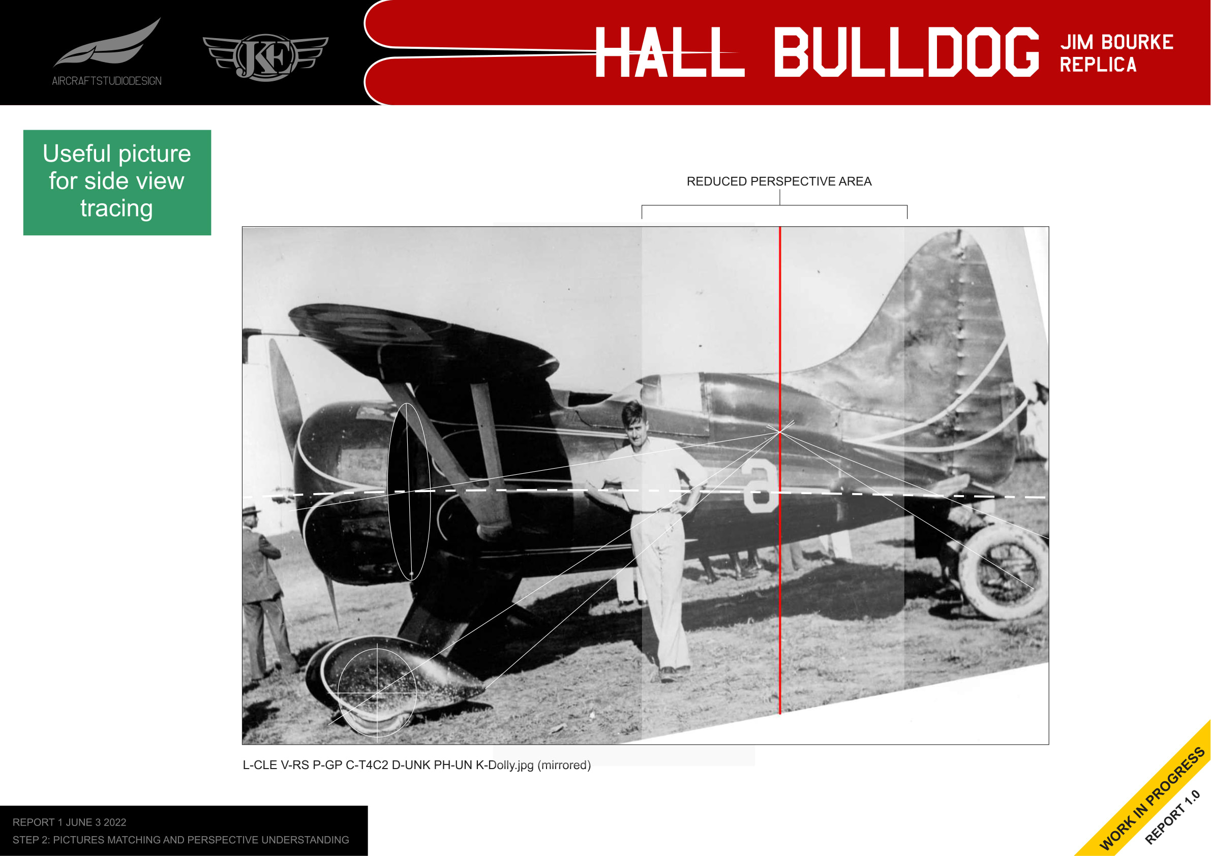
One method used is tracing pictures to replicate the aircraft contour. To avoid mistakes from camera lens distortion, Mirco identified the vanishing point of each side-view picture to find areas where perspective doesn’t distort the lines too much.
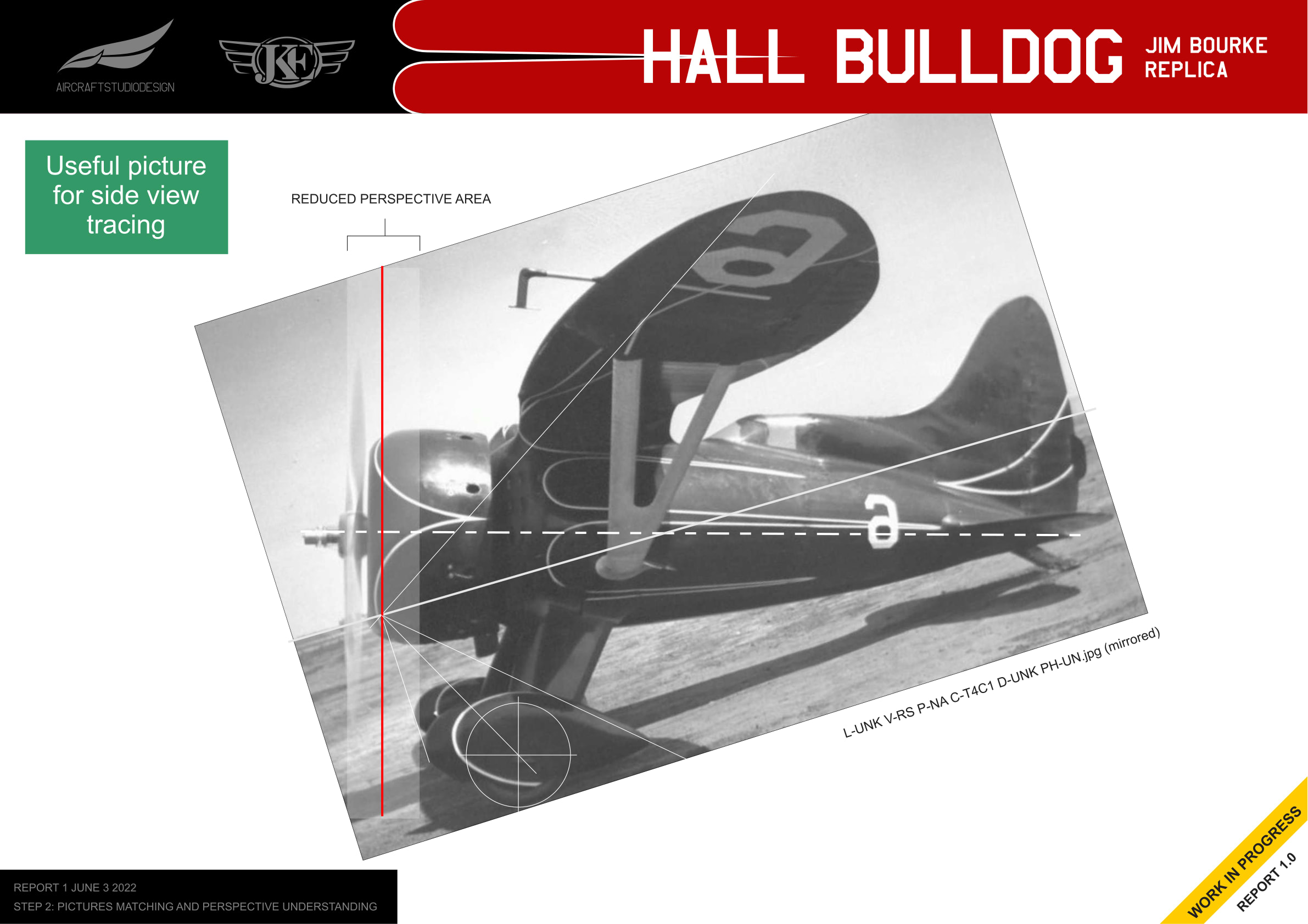
Multiple photos were selected because different portions show different parts with reduced perspective distortion. The first two photos from the left are good for tracing the cowling, and the last two are good for the fuselage, canopy and vertical empennage.
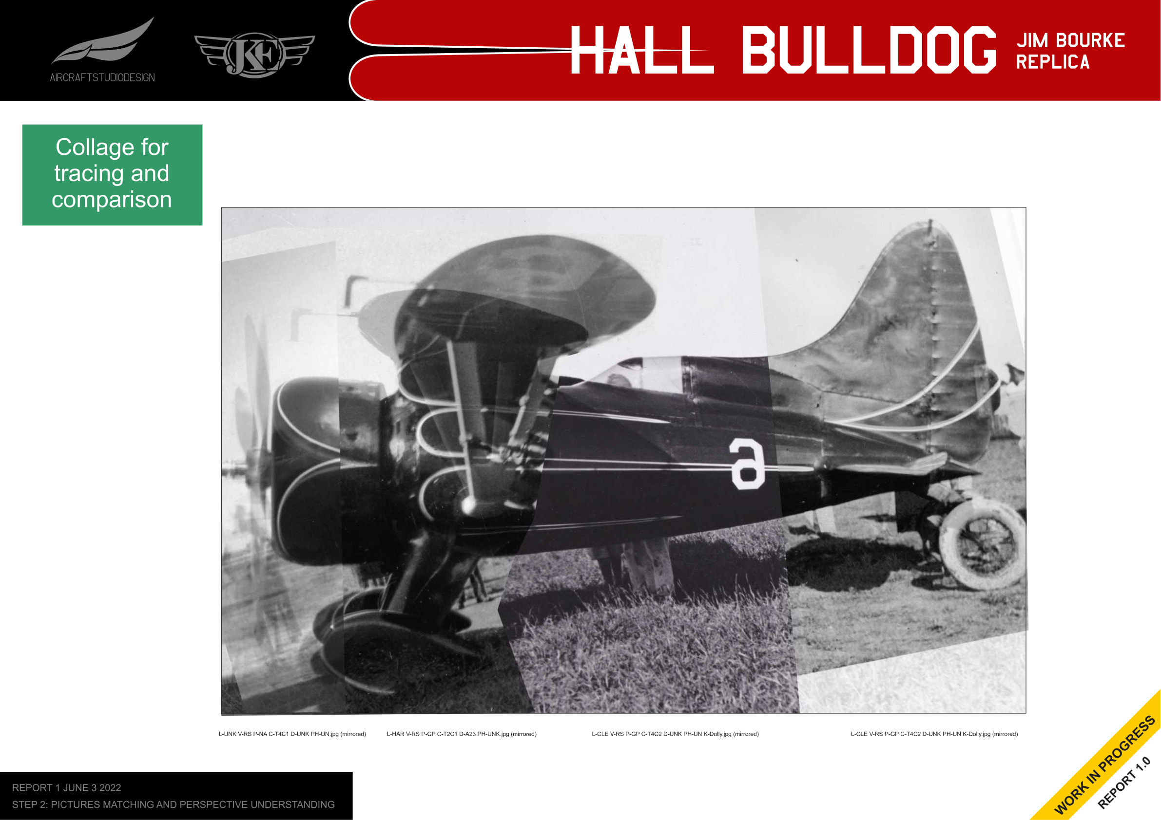
Creating a Photo Collage
By combining the distortion-free areas from multiple photos, a collage can be created that provides an accurate reference for tracing.
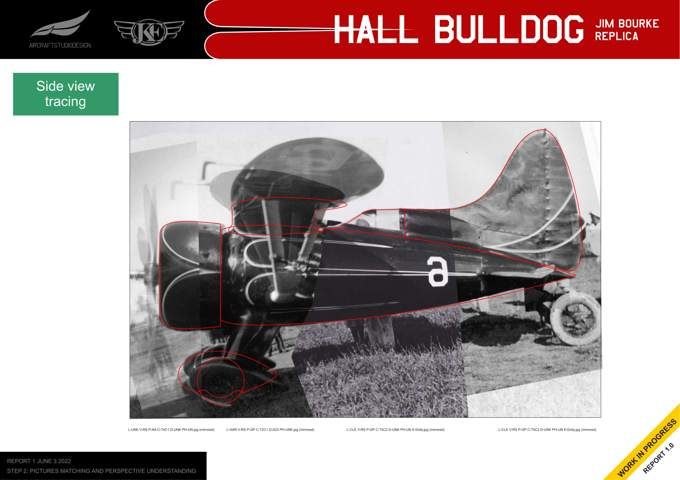
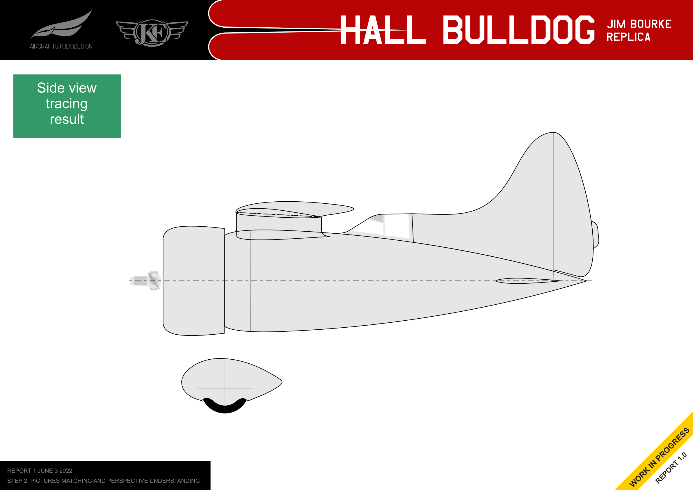
Side View Tracing
Using the photo collage, Mirco traced the outline of the aircraft to create an accurate side view drawing.
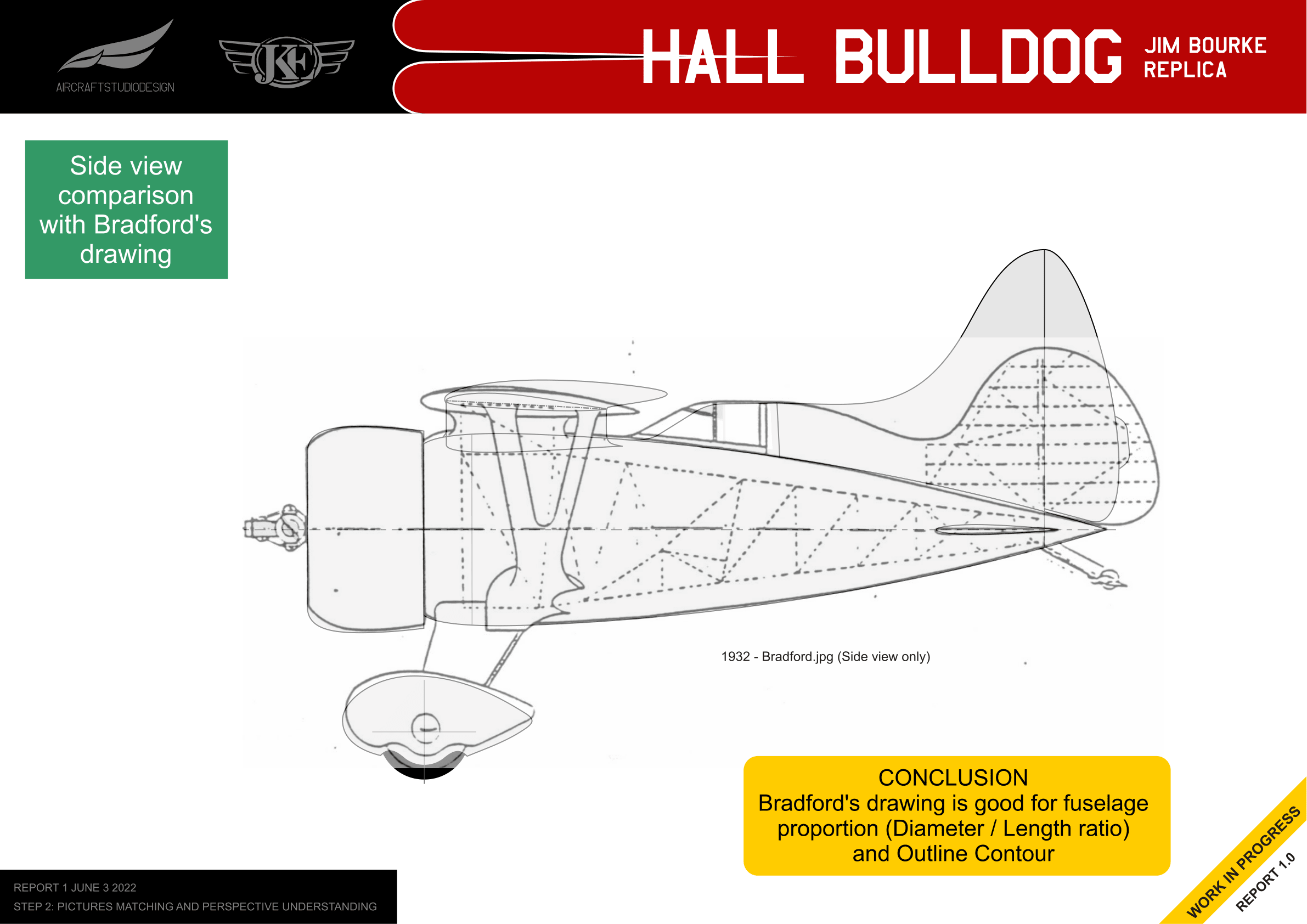
Comparison with Bradford’s Drawing
The traced side view was compared with Bradford’s 1932 drawing to validate the proportions.
Step 3: Draw 2 Dimensional 3 Views
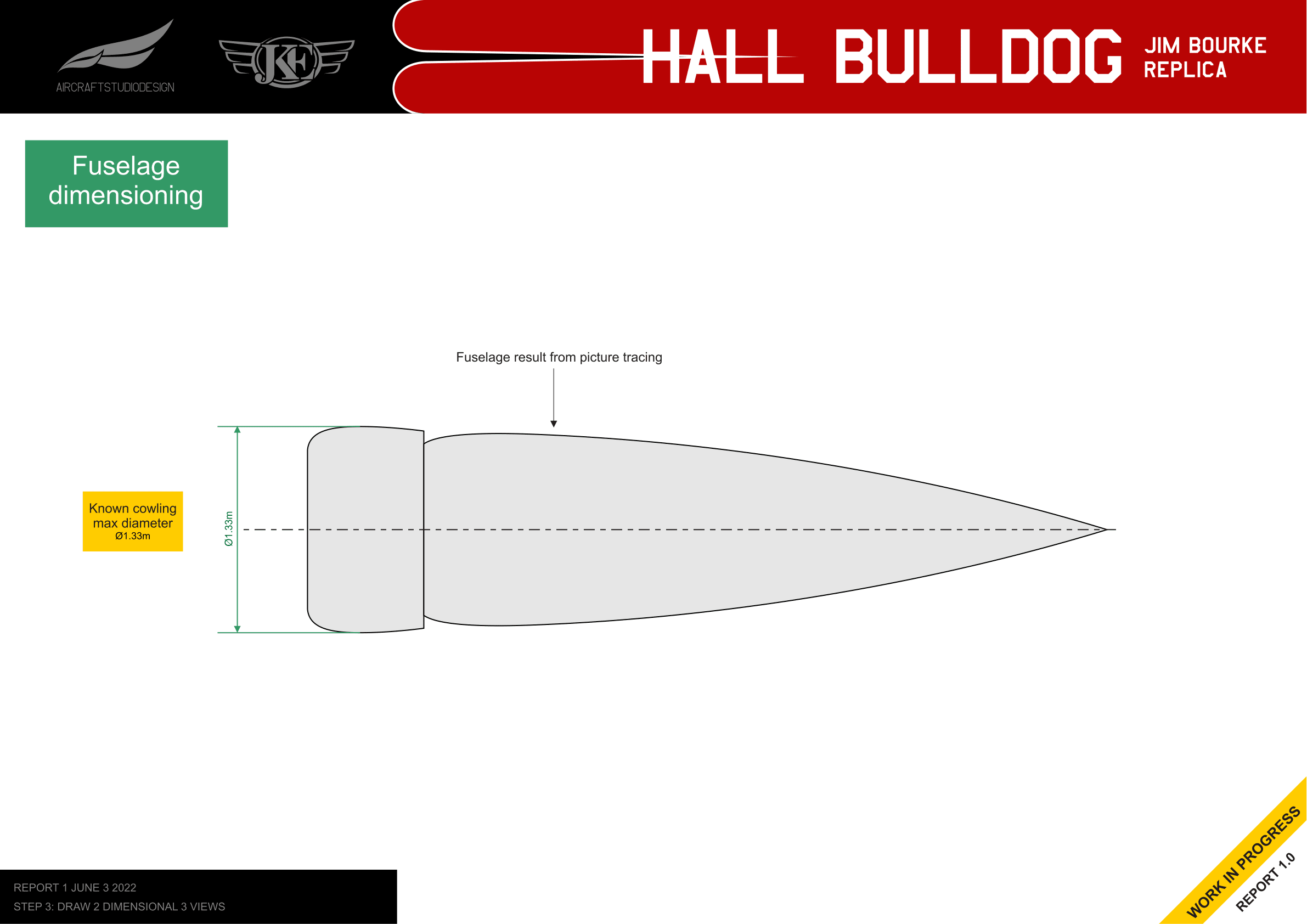
Fuselage Dimensioning
Using the known cowling maximum diameter of 1.33m, the fuselage proportions could be established.
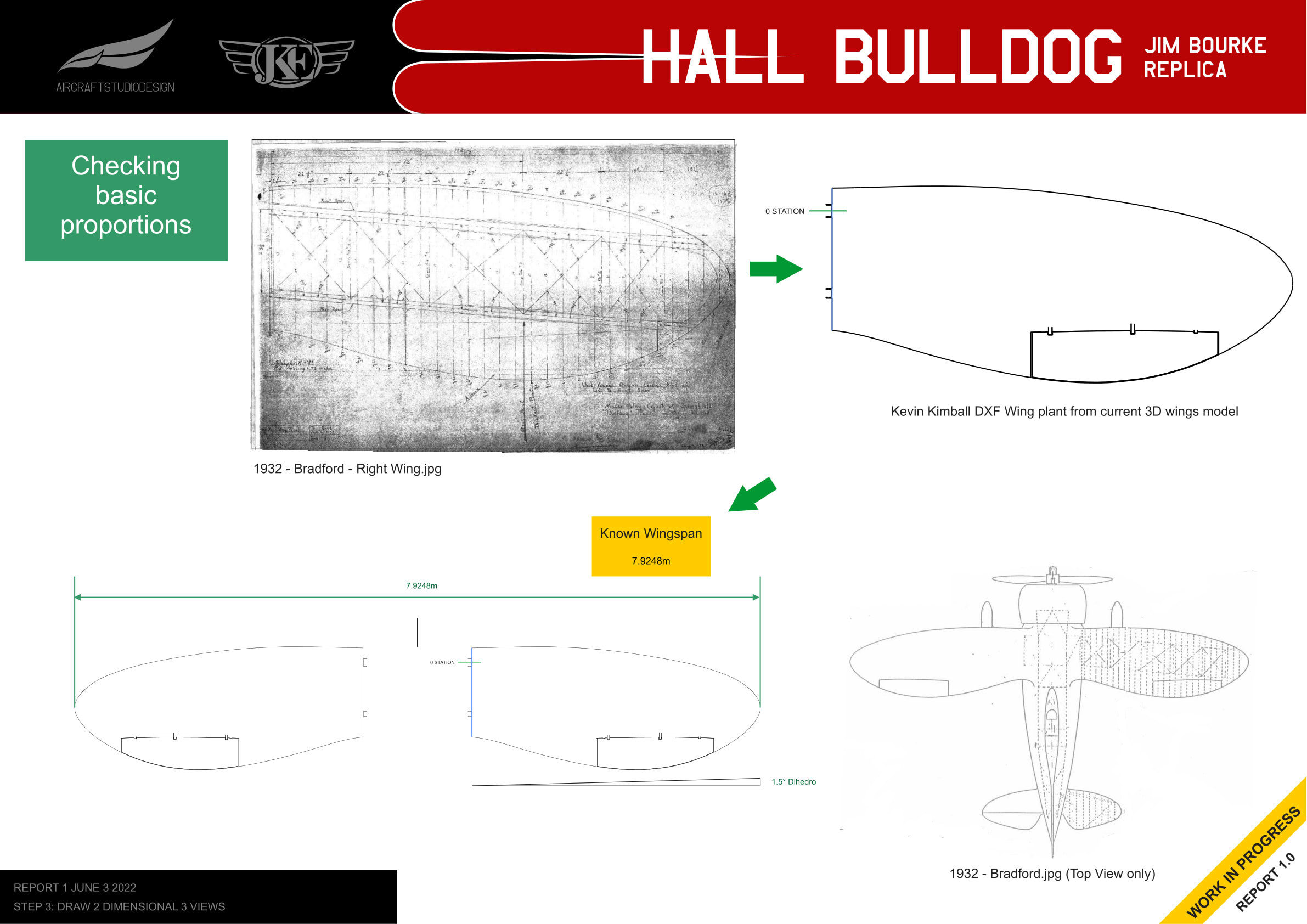
Wing Proportions
The wing proportions were checked against Bradford’s drawing and Kevin Kimball’s DXF wing model.
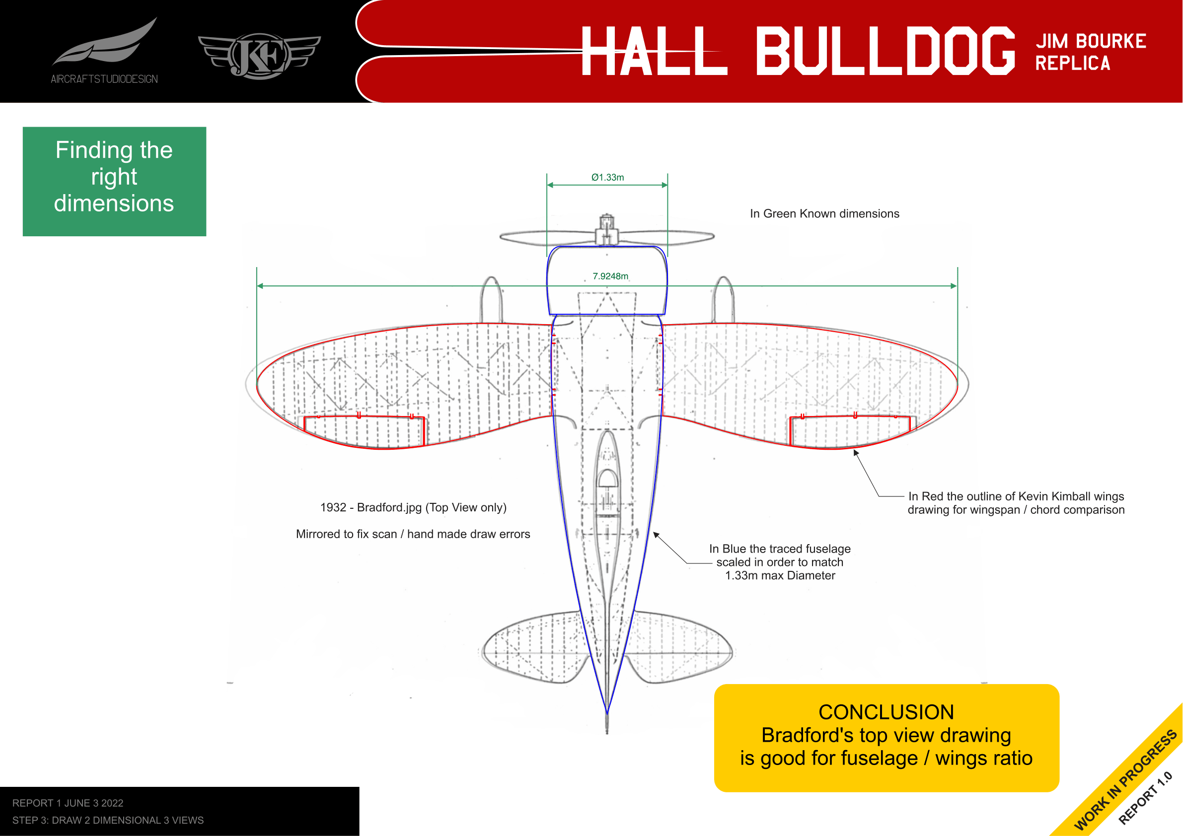
Finding the Right Dimensions
Using the known wingspan of 7.9248m and cowling diameter of 1.33m, the top view dimensions were established.
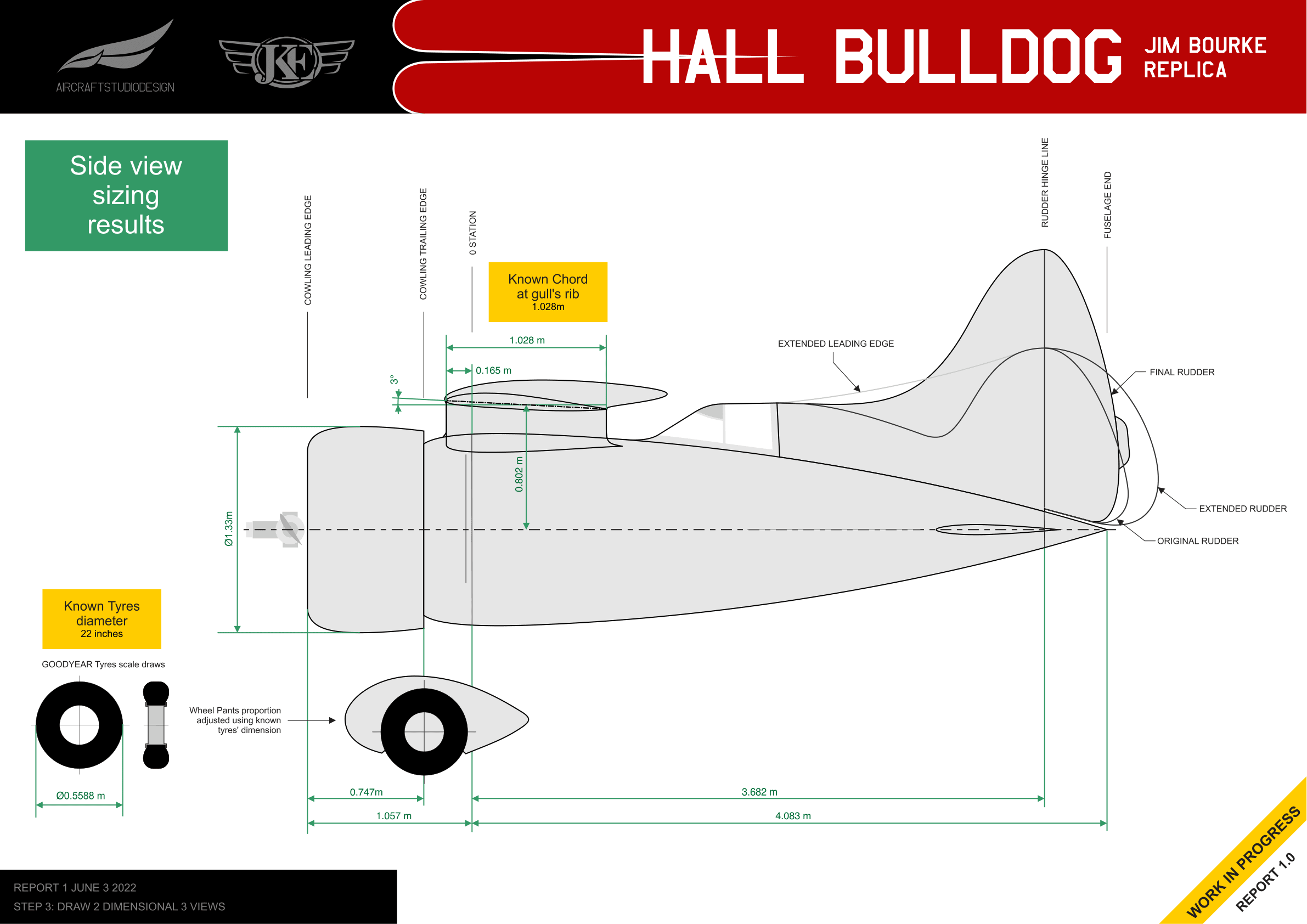
Side View Sizing Results
The final side view with all dimensions established:

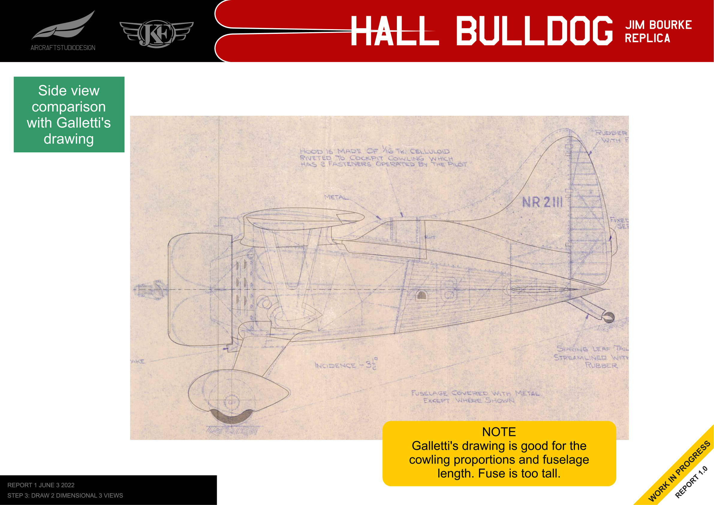
Comparison with Galletti’s Drawing
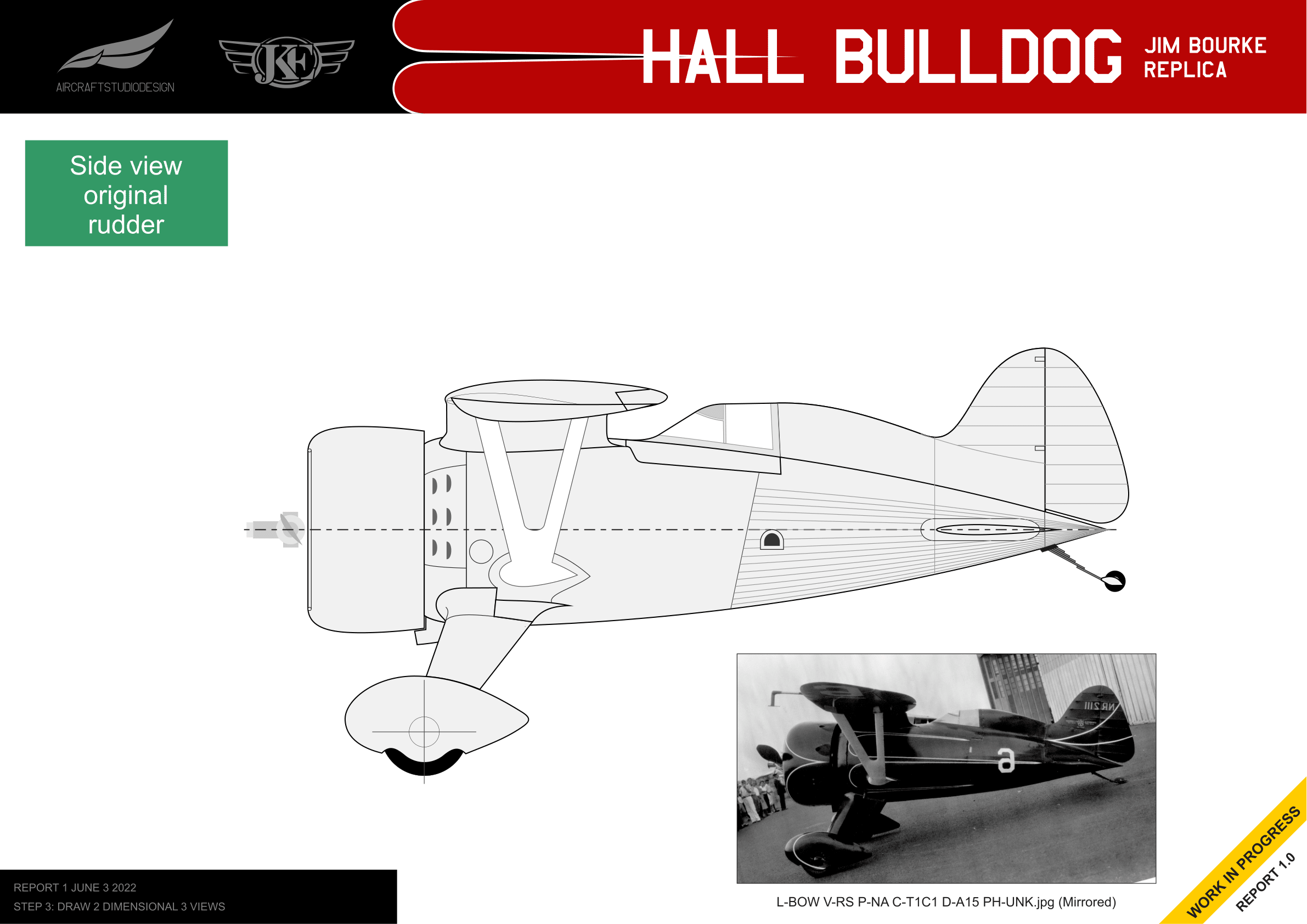
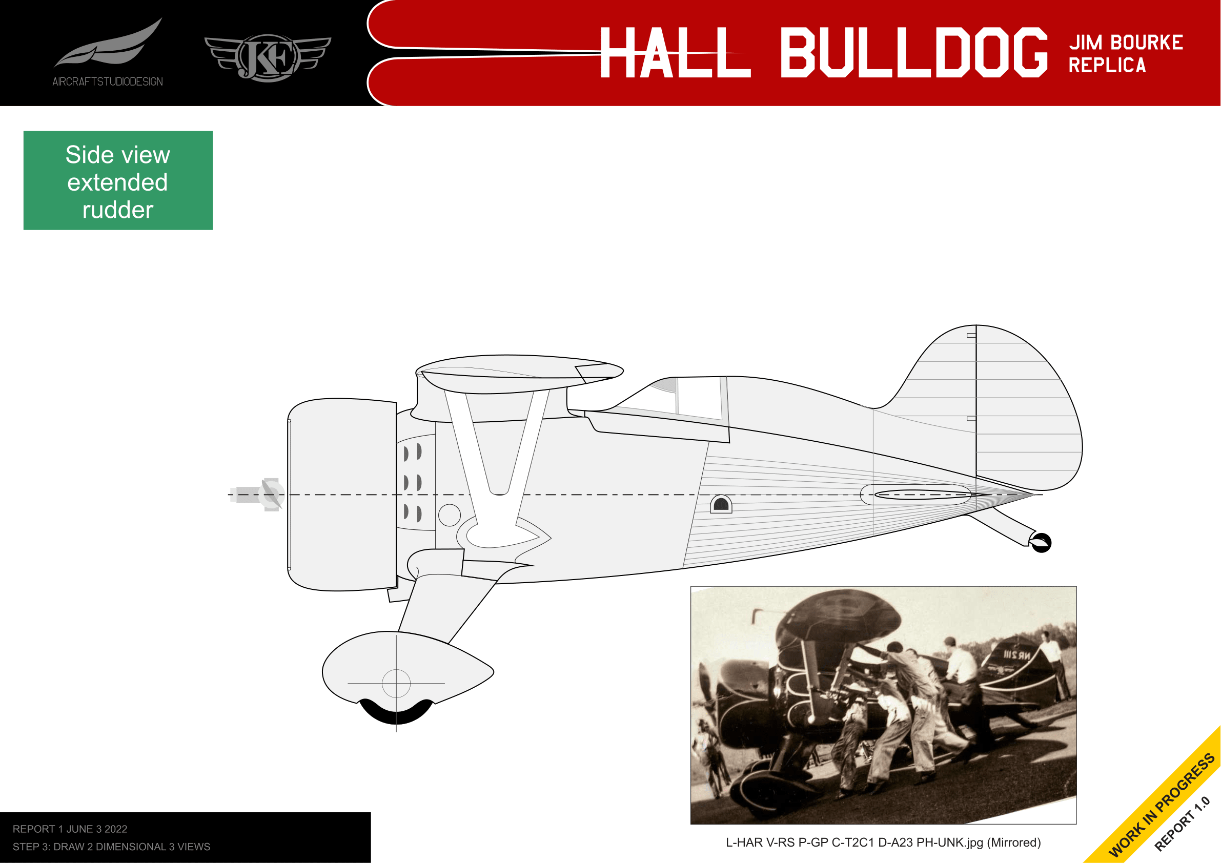
Tail Configuration Variations
The Hall Bulldog went through several tail configurations during its racing career. The 2D views document three versions:
Original Rudder
Extended Rudder
Extended Fin
Key Findings
- Bradford’s drawing is accurate for fuselage proportion (diameter/length ratio) and outline contour
- Bradford’s top view is accurate for fuselage/wings ratio
- Galletti’s drawing is accurate for cowling proportions and fuselage length, though the fuselage is too tall
- Known dimensions used: wingspan 7.9248m, cowling max diameter 1.33m, tire diameter 22 inches, chord at gull’s rib 1.028m
Related Reports
