Hall Bulldog 3D Modeling: Building and Validating the Model

Part of The Hall Bulldog Project — documenting Bob Hall's 1932 Thompson Trophy racer.
Explore the Project →This is the third report from Mirco Pecorari of Aircraft Studio Design, documenting the 3D modeling process for the Hall Bulldog replica project.
Steps 4 and 5: Modeling and Validation
This report covers Steps 4 and 5 of the design process, which are performed simultaneously:
- Step 4: 3D Modeling Based on 2D 3 Views - Building the actual 3D model
- Step 5: Comparison Between 3D Model and Pictures - Validating accuracy using historical photos
The Modeling Approach
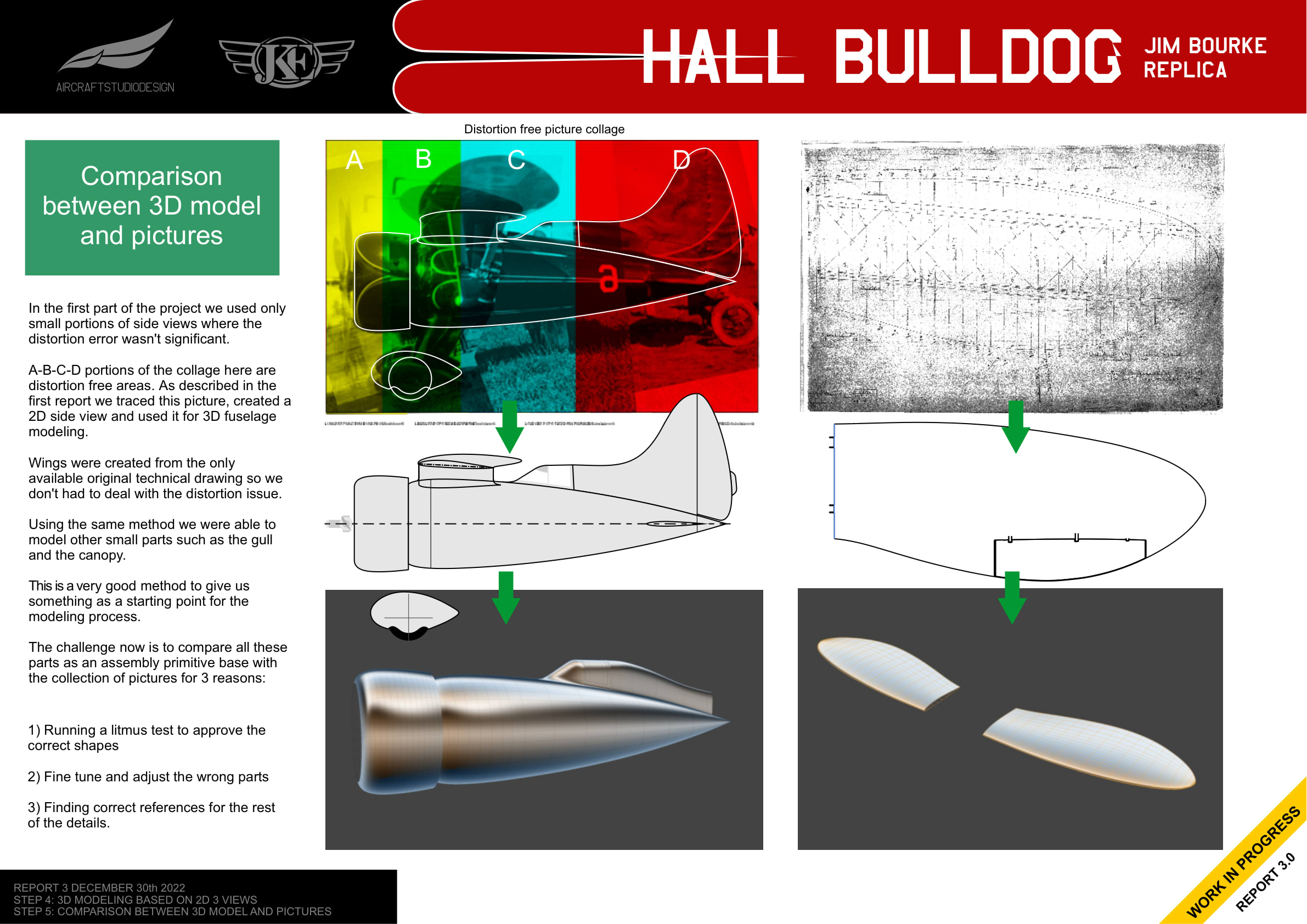
In the first phase of the project, only small portions of side views were used where distortion error wasn’t significant. The portions labeled A-B-C-D in the collage are distortion-free areas. The fuselage was traced from these areas and used for 3D modeling.
Wings were created from the only available original technical drawing, avoiding the distortion issue. The same method was used to model other parts such as the gull wing center section and canopy.
Reverse Engineering Method
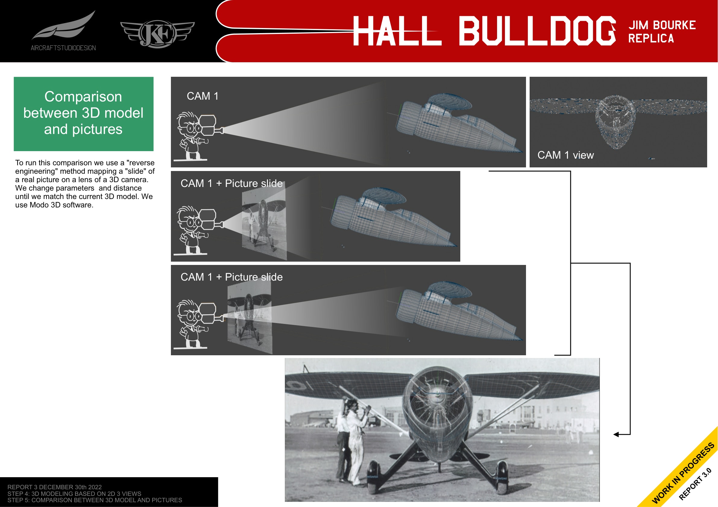
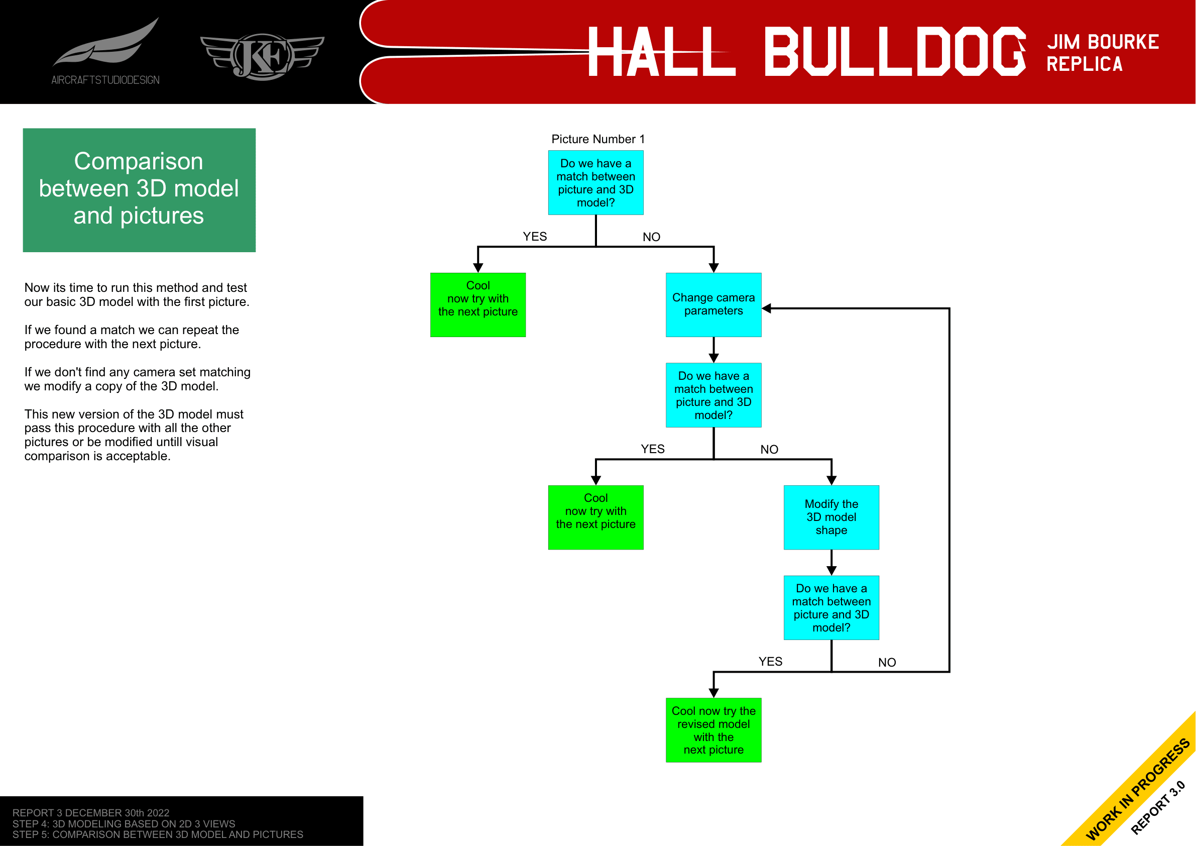
To compare the 3D model with historical photos, Mirco uses a “reverse engineering” method in Modo 3D software:
- Map a historical photo (“slide”) onto a virtual camera lens
- Adjust camera parameters (focal length, distance, position) until the 3D model aligns with the photo
- If no match is found after adjusting the camera, modify the 3D model
- Test the revised model against all other photos
- Iterate until the model matches all available photographs
Challenges with Historical Photos
Working with 1930s photography presents several challenges:
- Distortion - Old photos are often scanned or captured by another camera not aligned with the original plane
- Missing metadata - No information about lens type, exact distance, or lens distortion
- Poor resolution - Limited detail in many images
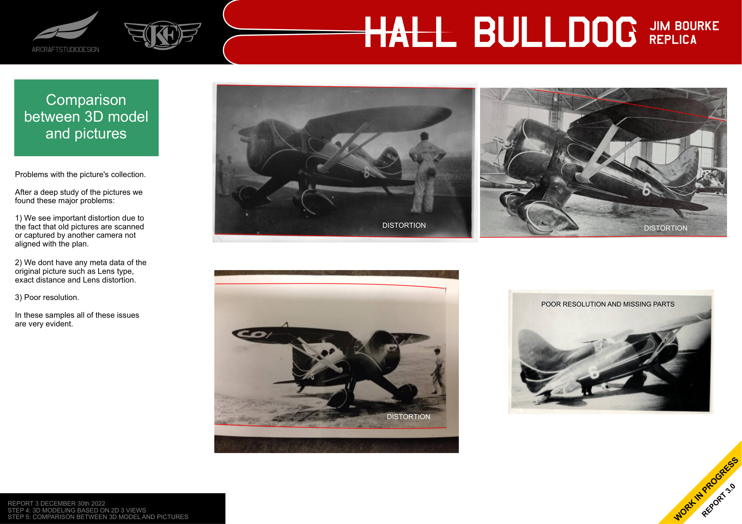
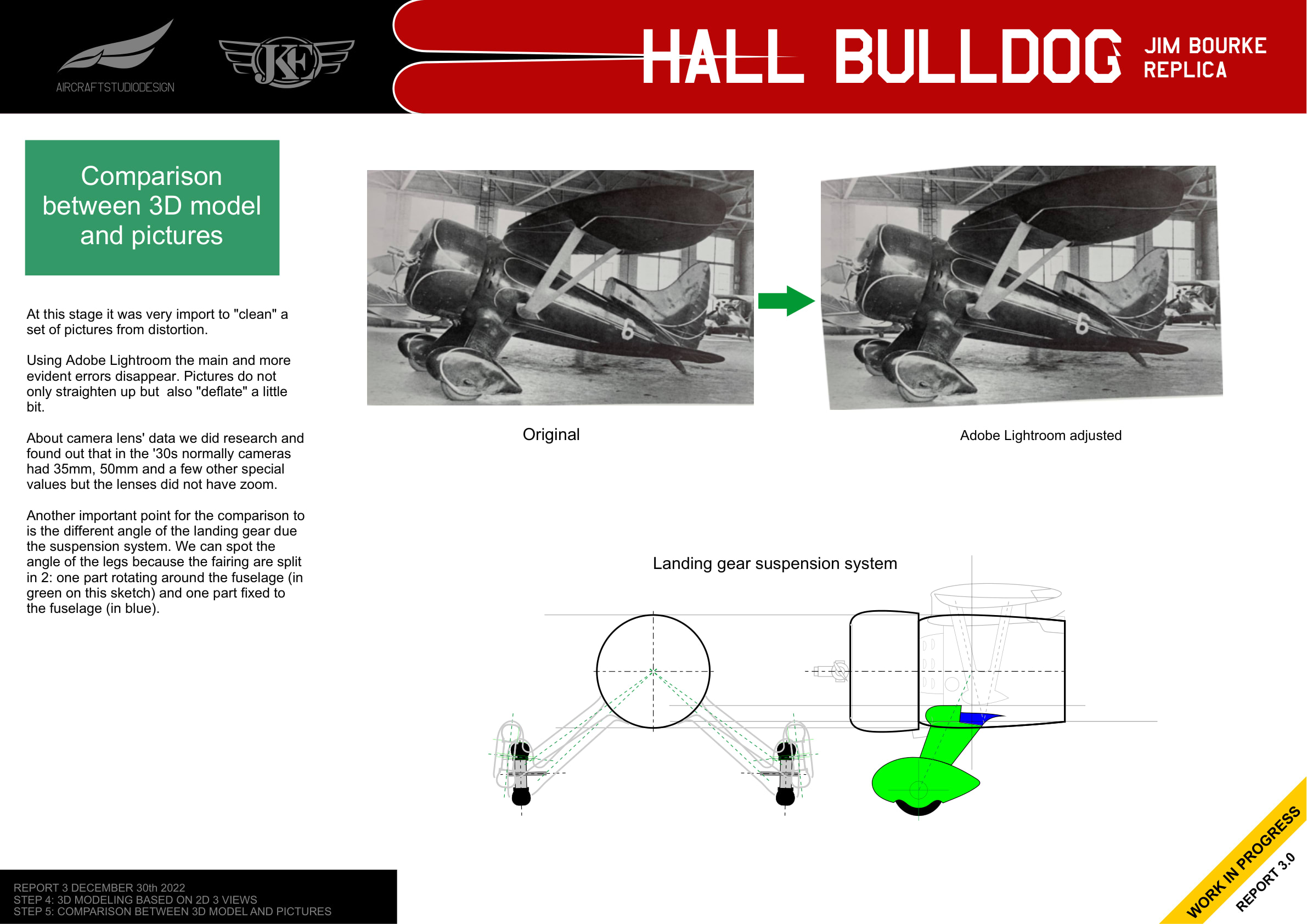
Using Adobe Lightroom, the team corrected the most evident distortion errors, straightening and “deflating” the images. Research indicated that 1930s cameras typically used 35mm or 50mm fixed lenses without zoom.
Landing Gear Considerations
An important factor in photo comparison is the landing gear suspension system. The angle of the legs varies depending on the aircraft’s weight, as the fairings are split: one part (shown in green) rotates around the fuselage while another part (shown in blue) remains fixed.
The Iterative Process
The validation process follows a systematic flowchart:
Results: 15 Iterations Later
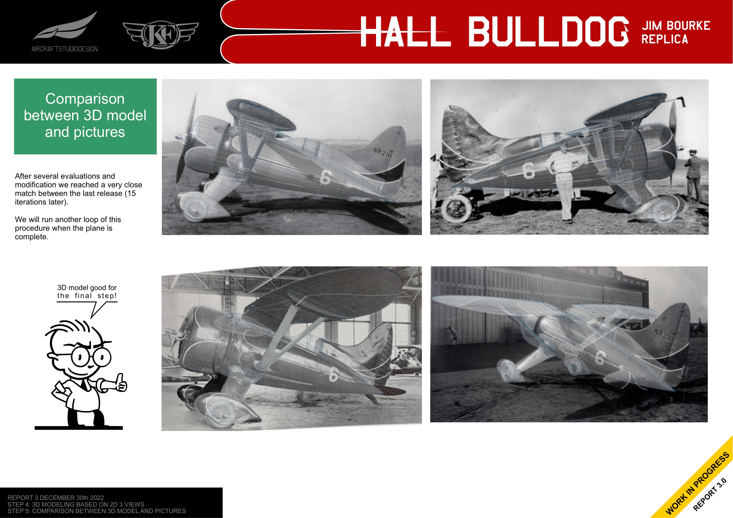
After several iterations (15 versions), the team achieved a close match between the 3D model and multiple historical photographs from different angles.
Marriage with Internal Structure
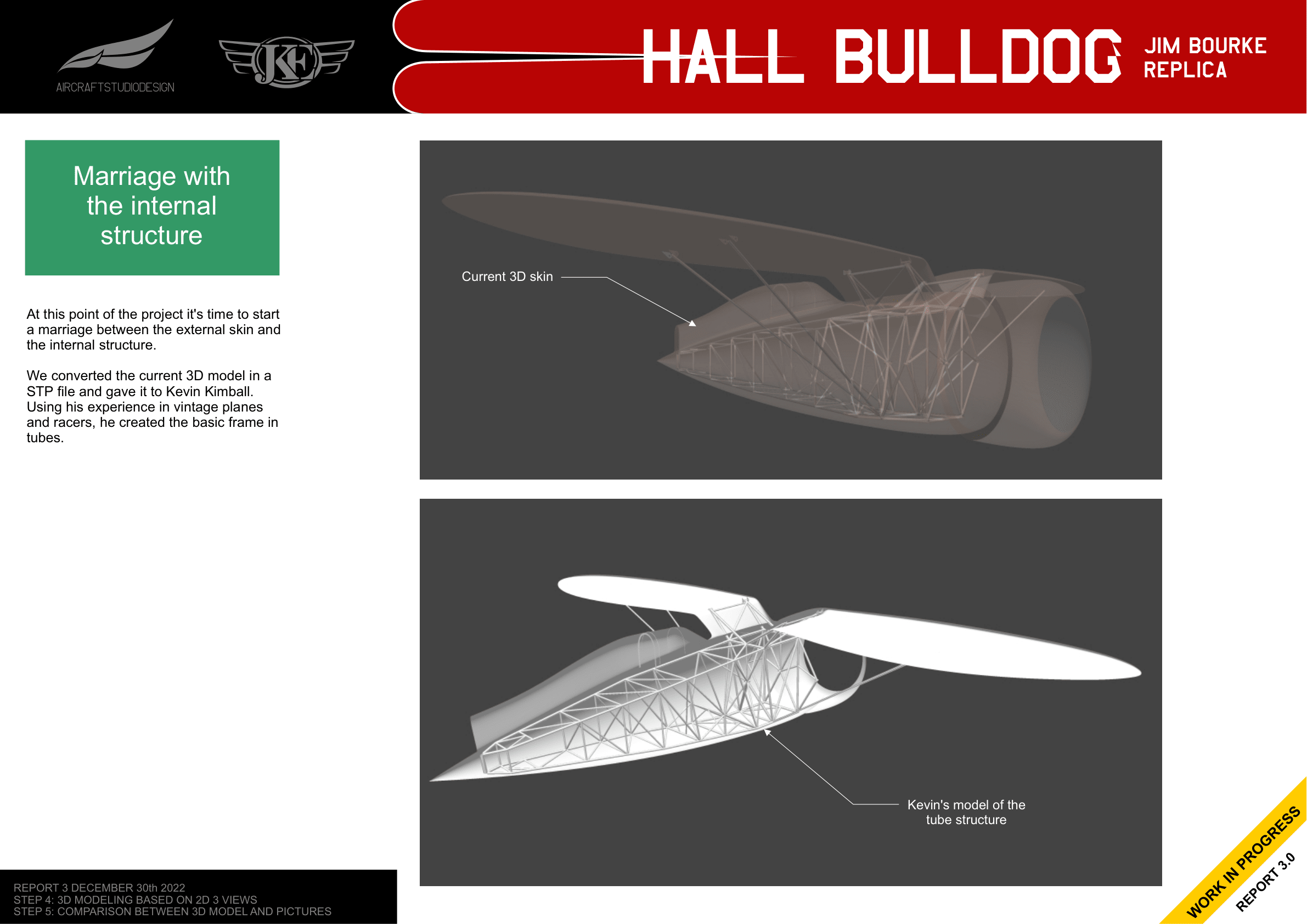
With the external skin validated, the 3D model was converted to a STEP file and shared with Kevin Kimball. Using his experience with vintage planes and racers, Kevin created the basic tube frame structure for the fuselage.
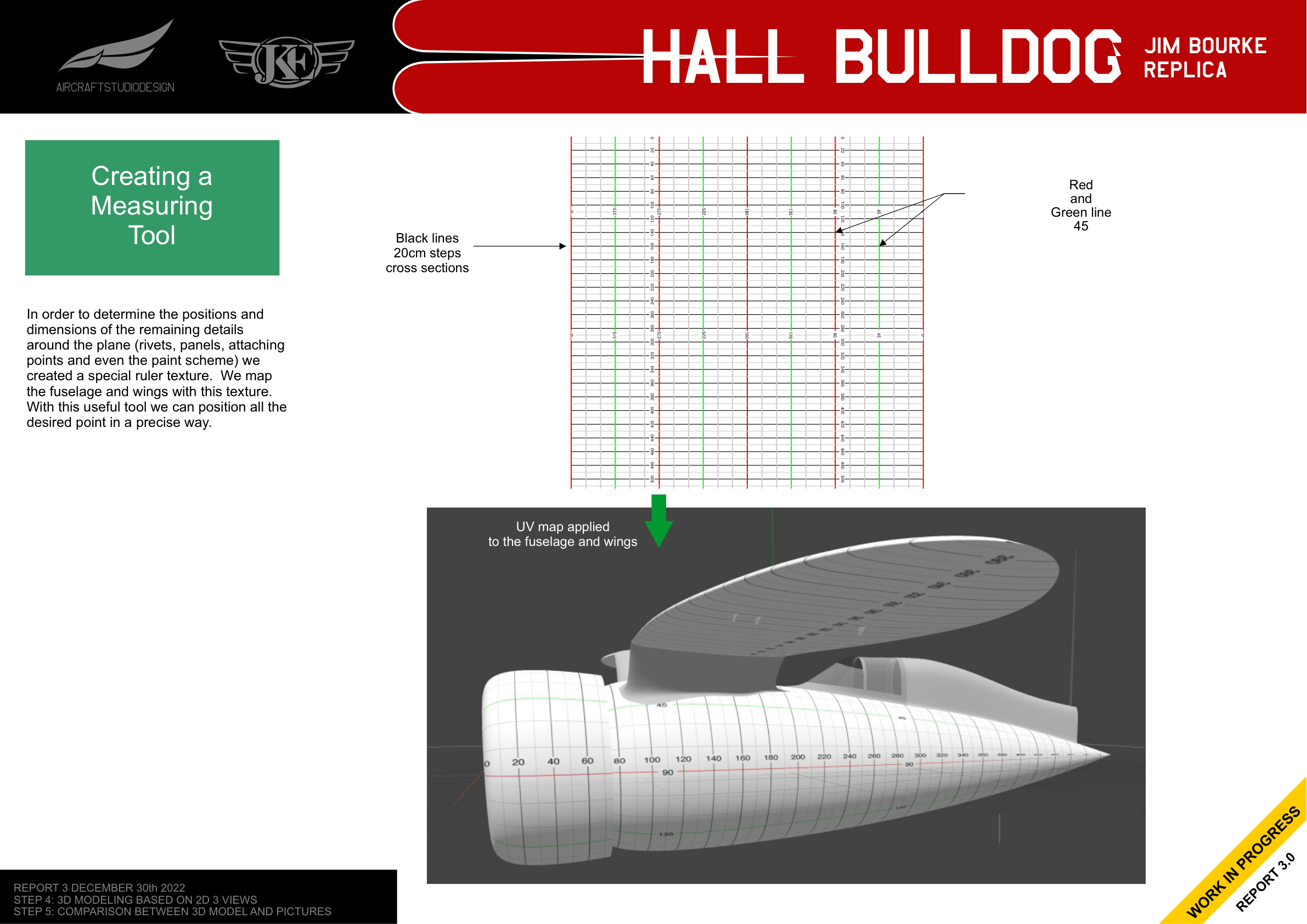
Measuring Tool
To position remaining details (rivets, panels, attachment points, and paint scheme), a special ruler texture was created. This UV map provides 20cm cross-section lines and 45-degree reference lines, allowing precise positioning of all elements on the curved surfaces.
Related Reports
