Hall Bulldog Aileron Linkage and Fuselage Frame Design - November 2021

Part of The Hall Bulldog Project — documenting Bob Hall's 1932 Thompson Trophy racer.
Explore the Project →This comprehensive engineering update from Kevin Kimball covers significant progress on the Hall Bulldog replica, including refined aileron linkage design and the initial fuselage tube frame CAD model. The update details the engineering decisions behind modern interpretations of 1930s control system designs.
Aileron Linkage Design
The aileron control system has been refined from the aileron through the inboard end of the wing. The bell crank geometry and attachment points are set pending full control system design checks.
Bell Crank and Pushrod System
The aileron control uses a pushrod system with bearing-mounted bell cranks for slop-free positive control, similar to modern aerobatic aircraft:

Aileron Idler
An idler is positioned midway between the aileron and the inboard end of the wing. This is common in pushrod control systems to reduce the length of the pushrods, avoiding buckling under compression loads:

Aileron Hinge System
The aileron hinge design required careful engineering due to the complex geometry of the elliptical wing with its M6 airfoil section.
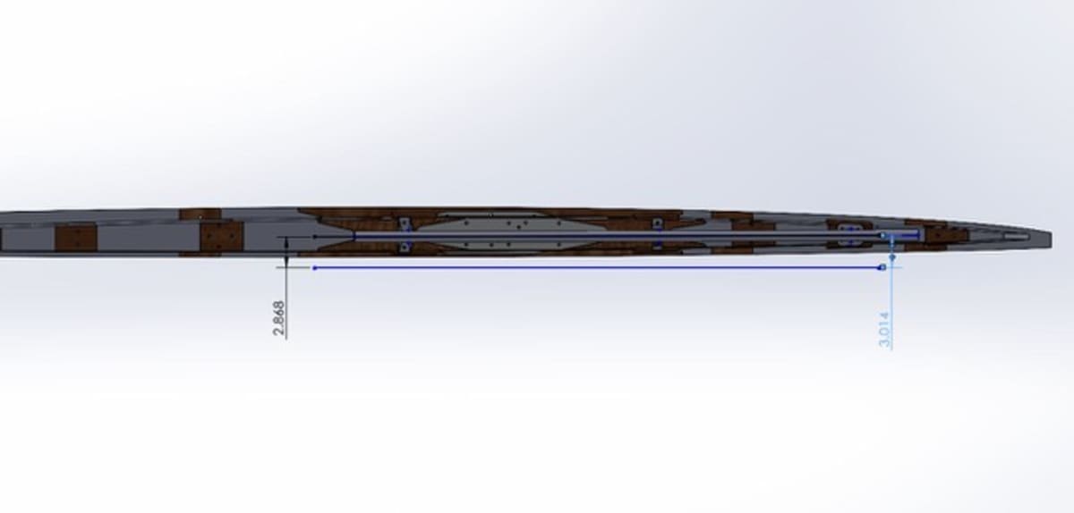
The Geometry Challenge
While the aileron hinge line is perpendicular to the aircraft centerline and wing ribs in top view, the chordwise view reveals how the aileron spar/hinge line runs uphill as it goes outboard. This is the result of:
- The inboard and outboard ends of the aileron needing to be within the M6 airfoil shape but at different percentages of chord length due to the elliptical wing planform
- The wing spars sweeping aft 5 degrees
- Washout twist in the wing for stability

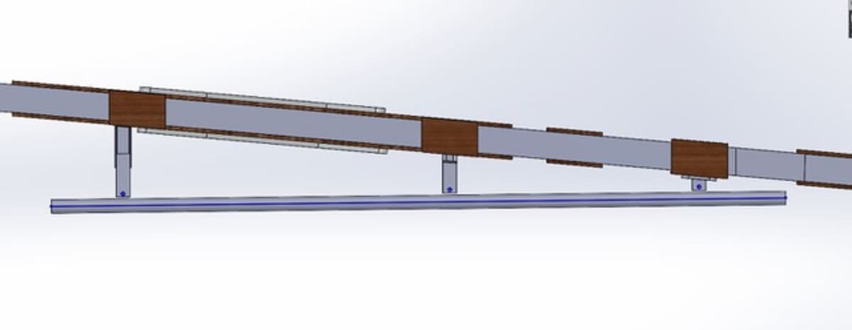
Strap Hinge Design
The original Bulldog likely used strap-type hinges, as Bob Hall employed this design on his previous work at Granville Brothers. Strap hinges were the norm in that era for tail feathers and ailerons, and are still used today on Pitts-style designs and bush planes.
The replica uses a removable, multi-piece hinge design inspired by later Beech Staggerwing hinges, allowing for serviceability while maintaining performance:

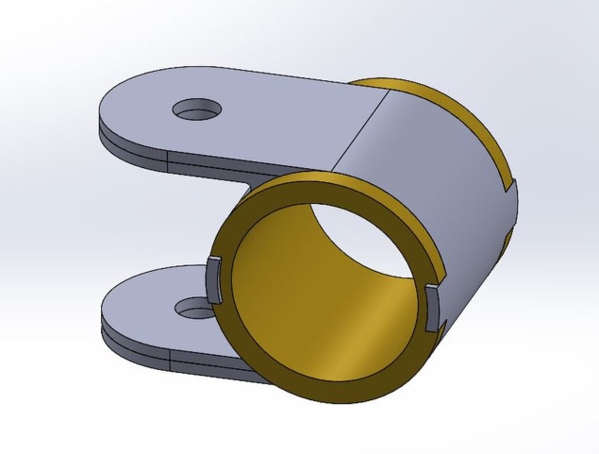

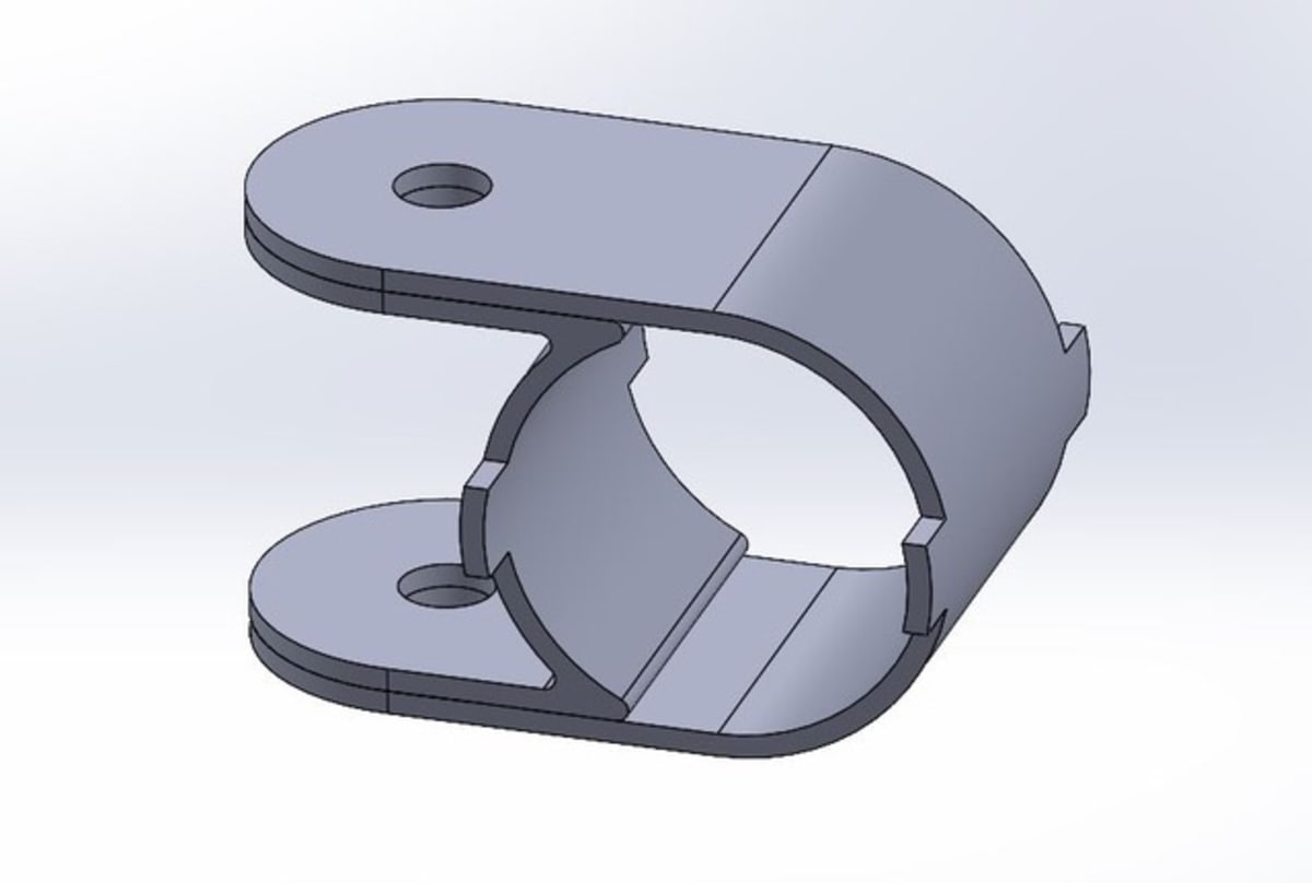

The hinge brackets attach to the rear wing spar and will be weldments from 4130 steel. The design uses a 1-inch spar tube for adequate torsional stiffness.
Fuselage Tube Frame Design
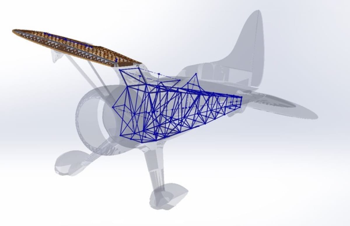
Work has begun on the 3D CAD model of the fuselage structure, based on collected data, photos, and references. The fuselage frame CAD model is fully parametric, allowing tubes or entire sections to be moved with all tube lengths, angles, and end trim shapes updating automatically.
Frame Geometry
The fuselage frame is positioned inside the surface model derived from the 3D rendering work by Mirco Pecorari:

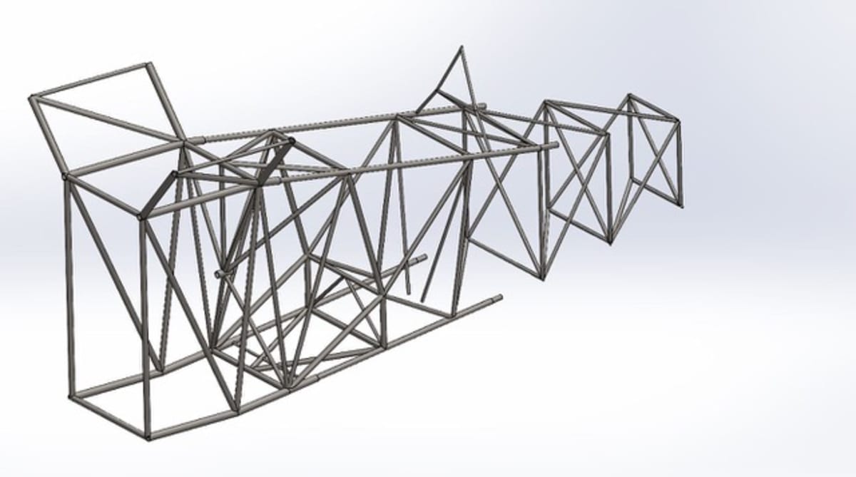
Frame Views


Design Notes
Key observations about the fuselage frame:
- Target weight: 100 lbs for the welded fuselage frame, comparable to the Granville Brothers Z frame and Stearman frames
- Narrow design: The frame is very narrow given the plump fuselage shape when fairings, metal, and fabric are installed. Hall designed it this way to allow for large D-shaped fuel tanks along the left and right sides
- Center-pivoting gear: The main gear legs pivot in the aircraft centerline, a unique feature that Bob Hall later used in the Stinson SR series
- Gull sections: Have only main tubes in place until locations, lengths, and angles are adjusted to match wing attach fittings and incidence angle
Once the frame is fully defined with all tubes, a load analysis will determine which tubes need to be larger for the loads applied and which can be reduced in size/weight.
About Kevin Kimball
Kevin Kimball of JKE Works in Mount Dora, Florida is the structural engineer for the Hall Bulldog replica project. His experience includes work with Curtis Pitts (accepting Pitts’ induction into the ICAS Hall of Fame) and helping set up displays for legendary airshow performers including Jimmy Franklin, Bobby Younkin, Jim LeRoy, and the Shockleys.
