Hall Bulldog Wing Shape Revisions - January 2023

Part of The Hall Bulldog Project — documenting Bob Hall's 1932 Thompson Trophy racer.
Explore the Project →This engineering update from Kevin Kimball documents the revisions made to the Hall Bulldog CAD model to incorporate the refined surface model developed by Mirco Pecorari of Aircraft Studio Design. The updates ensure the structural design accurately matches the validated aircraft shape.
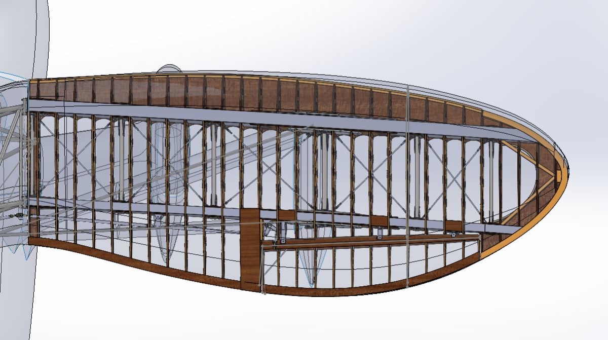
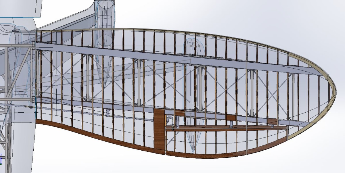
Wing Leading Edge Corrections
The most significant change involves the wing leading edge shape. Mirco’s photo analysis revealed that the original leading edge contour was different from initial assumptions, resulting in a much nicer look without the flat spot that appeared in earlier models.

Structural Implications
The leading edge changes require updates to several components:
New Nose Ribs
The revised leading edge shape requires new nose rib profiles. These will be cut from plywood using a CNC router. The rest of the built-up truss ribs will work with minor contour adjustments.

Wing Fittings Optimization
The wing fittings and draw wire plates have been updated to reduce weight and size while ensuring proper clevis pin installation from either direction:


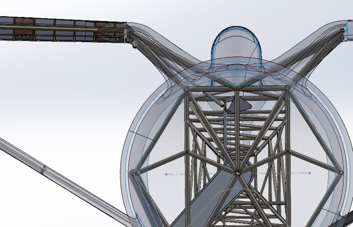
Strut Fitting Angle Change
The strut fitting angle has been changed from 33 degrees to 30 degrees to accommodate the revised wing geometry and lower wing attachment point:


Wing Attachment and Dihedral
Several key parameters have been adjusted based on Mirco’s refined analysis:
- Dihedral: Slightly different from the earlier Josh/Vern model - a bit more than previously estimated
- Wing attach point: Lower than the Vern data indicated, now fitting inside Mirco’s skin model
- Gull section tubes: Now properly positioned inside the Mirco gull skin model
Summary of Changes
| Parameter | Previous Value | Updated Value |
|---|---|---|
| Strut fitting angle | 33 degrees | 30 degrees |
| Wing dihedral | Josh/Vern estimate | Increased per Mirco |
| Wing attach height | Higher | Lowered to fit Mirco model |
| Leading edge shape | Flat spot present | Smooth contour |
Collaborative Design Process
This update represents the ongoing collaboration between Aircraft Studio Design’s 3D modeling expertise and Kevin Kimball’s structural engineering experience. The iterative process of refining the surface model and updating the structural design ensures the replica will be both visually accurate and structurally sound.
About Kevin Kimball
Kevin Kimball of JKE Works continues to refine the Hall Bulldog structural design, incorporating feedback from the 3D modeling team while preparing deliverables including updated nose rib shapes, spar models, and tip bow shapes for builder Tony Horvath.
