Plane Tracking Camera Project

Editor’s note: The article date on this blog tells the reader when the pictures were taken, but I’m actually typing this in early 2026.
My experience with having people video record my flights has been frustrating:
- Everyone wants to use an iPhone. It can’t zoom in enough.
- If you give an amateur a camera that can zoom in enough, you will get such shaky video it’s hard to see the subtle issues in your flying. This is what led me to make MotionCrop.
- If you hire a pro, you will get everything you dreamed of—at great expense.
Why Not Just Use MotionCrop?
I found MotionCrop and an amateur camera person, combined with a great camera, was workable. But sometimes I wanted to go to the airport and put in a practice flight on my own. I started dreaming: wouldn’t it be nice to make a device that just sat on top of my hangar and every time I powered up and taxied away it would start recording me as long as I stayed within a few miles? That’s where this project was born.
It’s downright eerie to watch videos processed with MotionCrop because they are so ridiculously locked in it looks like computer generated imagery. I wanted the same thing without all the processing effort. The downside of MotionCrop is that it doesn’t handle smoke, clouds, or even gnats flying in front of the lens all that well. It gets confused because image processing isn’t a perfect science. And there is no hope of doing something like MotionCrop in realtime. Yet.
The Naive Beginning
I started out with all my engineering and math experience (which included some real science working with satellites back in my early days) but honestly, looking back, I was downright naive about how capable an inexpensive off-the-shelf IMU (inertial measurement unit) from a company like SparkFun could be. I bought several that were in the hundred to several hundred dollar range, and I bought some inexpensive radio transceivers and a couple of little processor boards.
The results were laughably bad. The IMUs had very shaky AHRS (attitude and heading reference systems) that resulted in the device thinking it was flying off into space at one million miles an hour when it was perfectly stationary. The GPS systems were accurate when they worked. The radio transceivers which promised miles of effective radius managed only a few dozen feet.
I started working on software solutions for the inertial system and eventually did enough work to realize it just wasn’t ever going to work the way I wanted with the equipment I had.
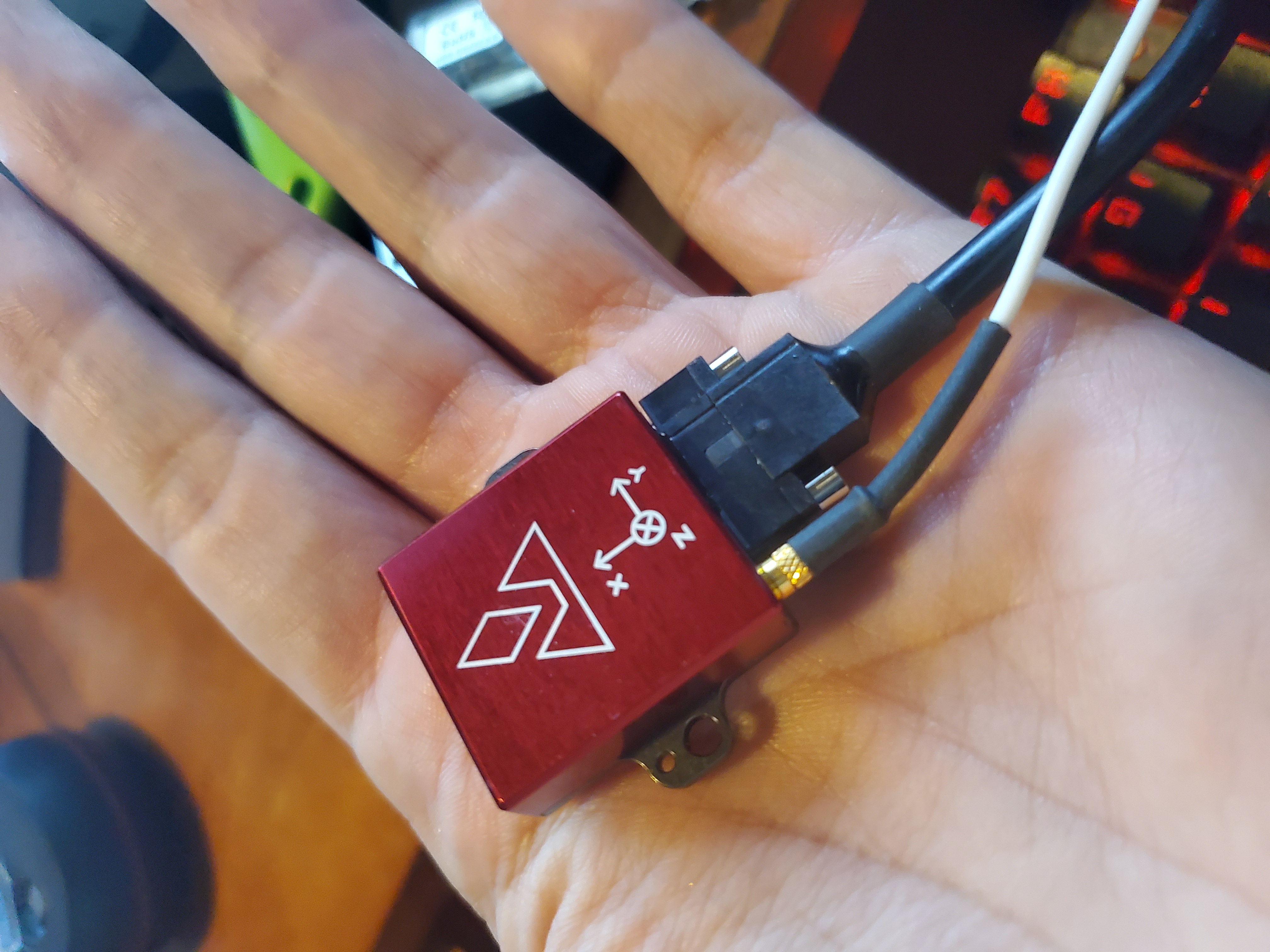
Enter VectorNav
I knew from previous conversations with engineers in the defense industry that the technology was there, so I made a few phone calls and got pointed to VectorNav.
I feel kind of bad writing this because I really owe them an apology. They gave me two state-of-the-art sensor systems and supported my work with the expectation that I would write a case study. Unfortunately, I didn’t follow through. I can blame the passing of my fiancee, Marianne, for a chunk of that, but I still wish I had resumed work on this and gotten them what they deserved.
My bad, VectorNav. I hope this late offering of text and photos makes up for it a bit. I still have your sensors and I still have all the equipment and code. You can link people to this article or I can write you a new one. Your products worked perfectly.
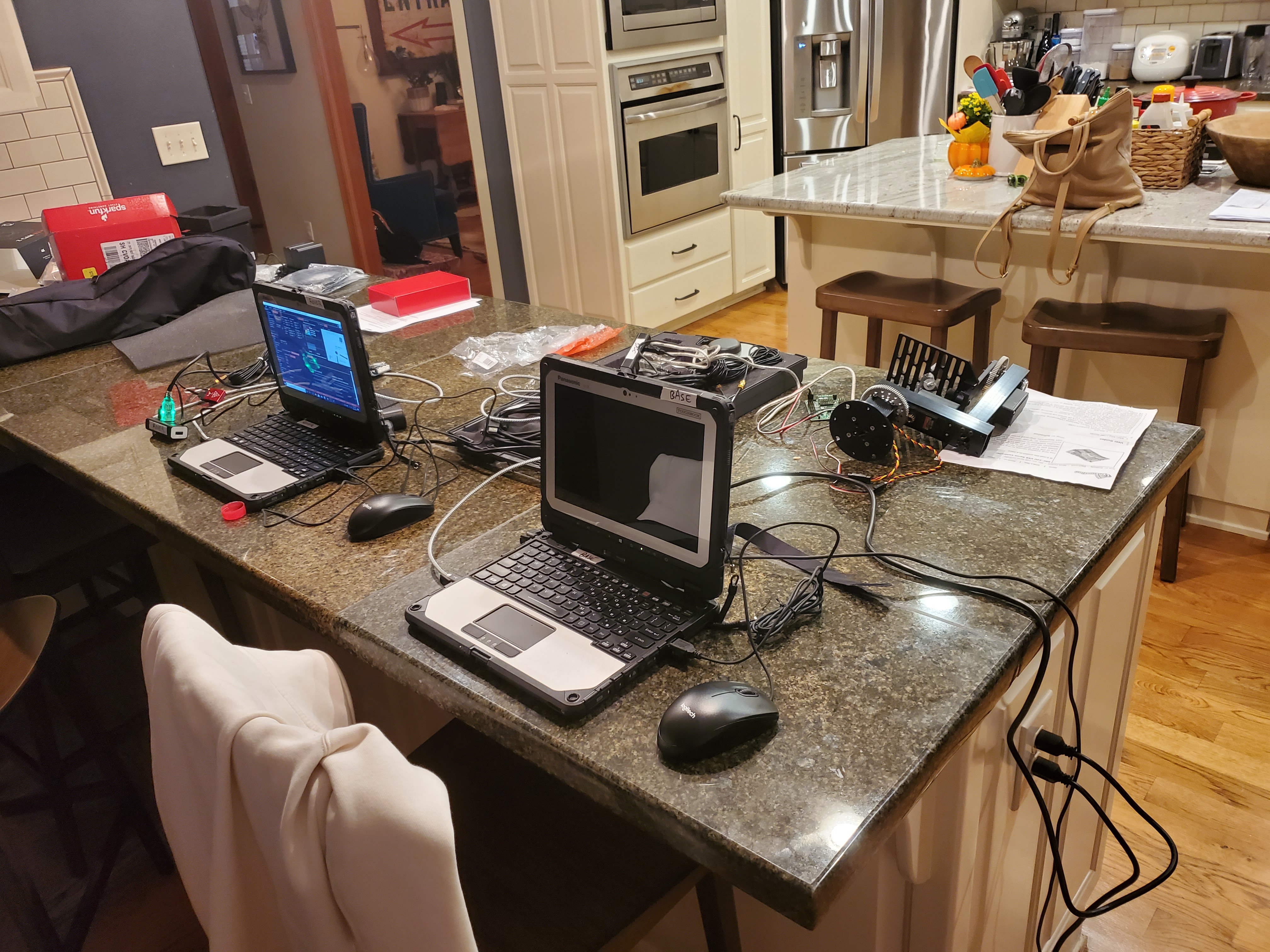
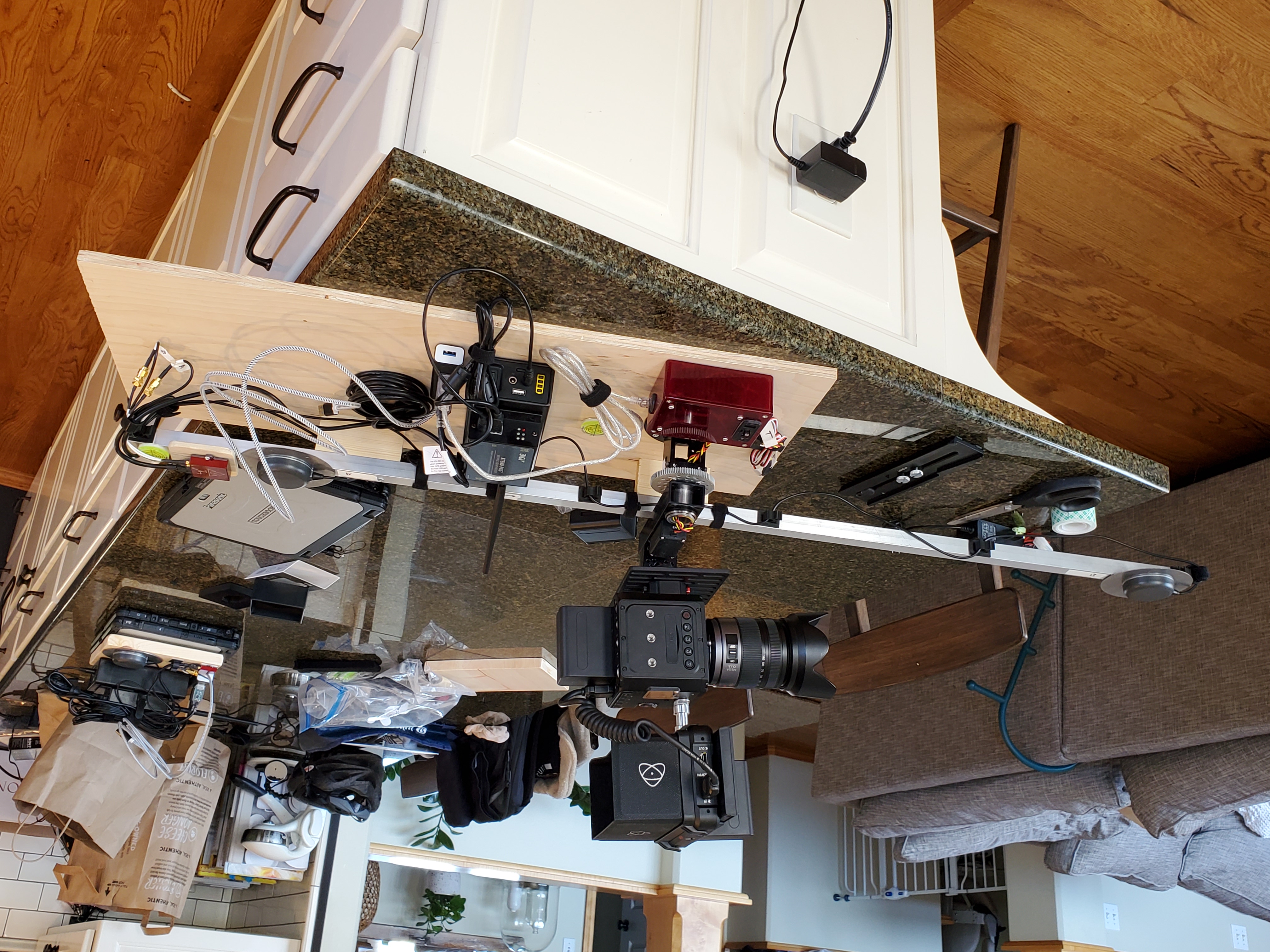
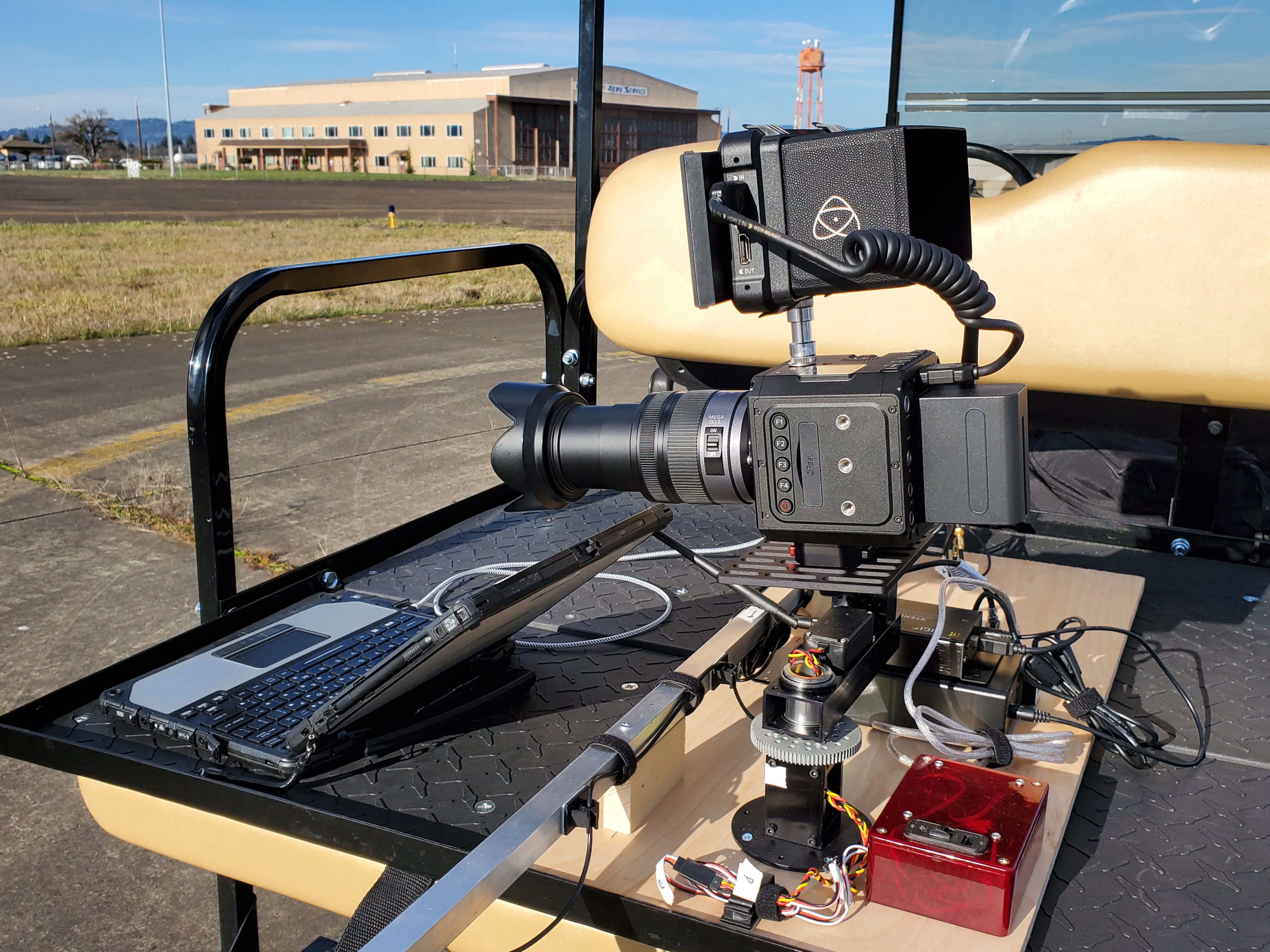
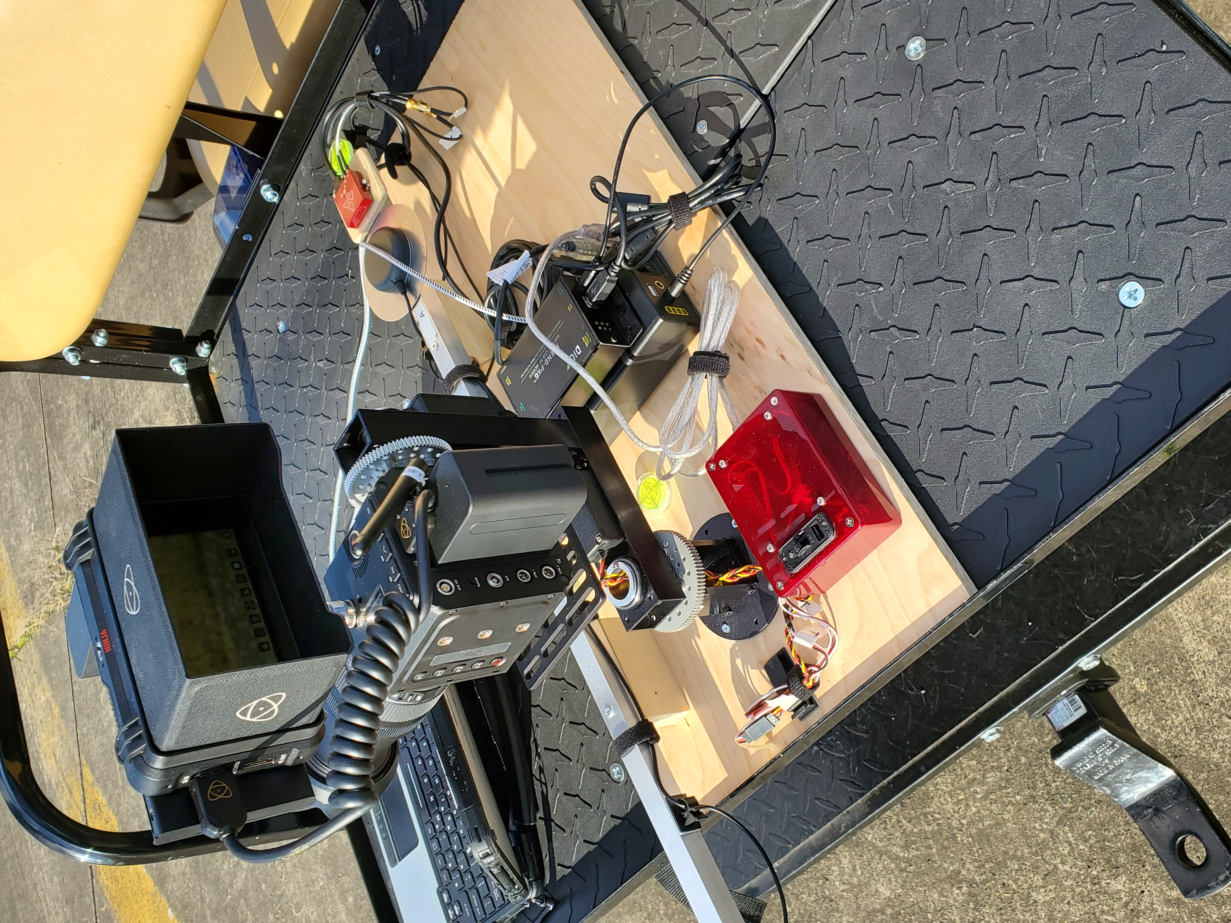
The Equipment Stack
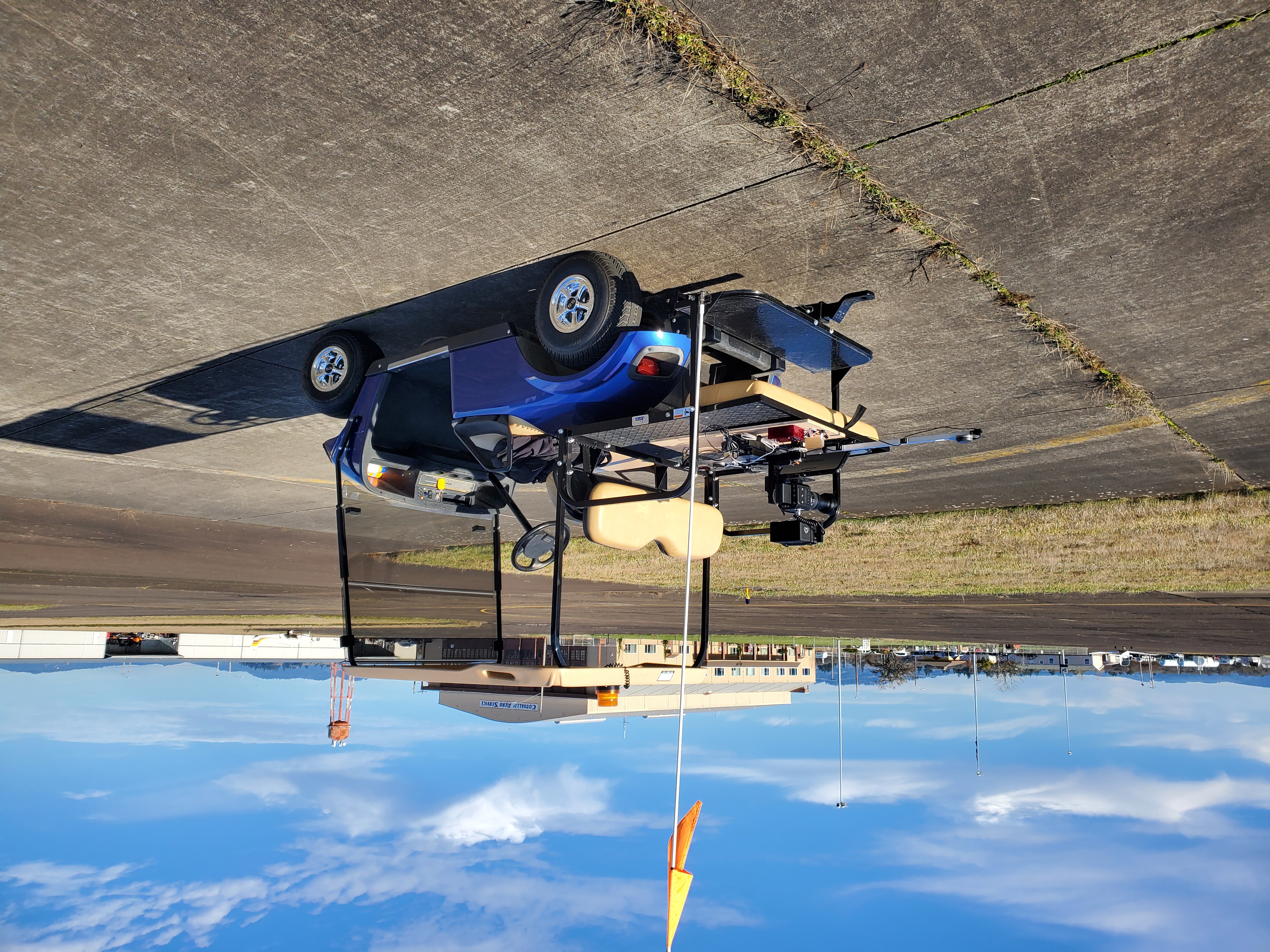
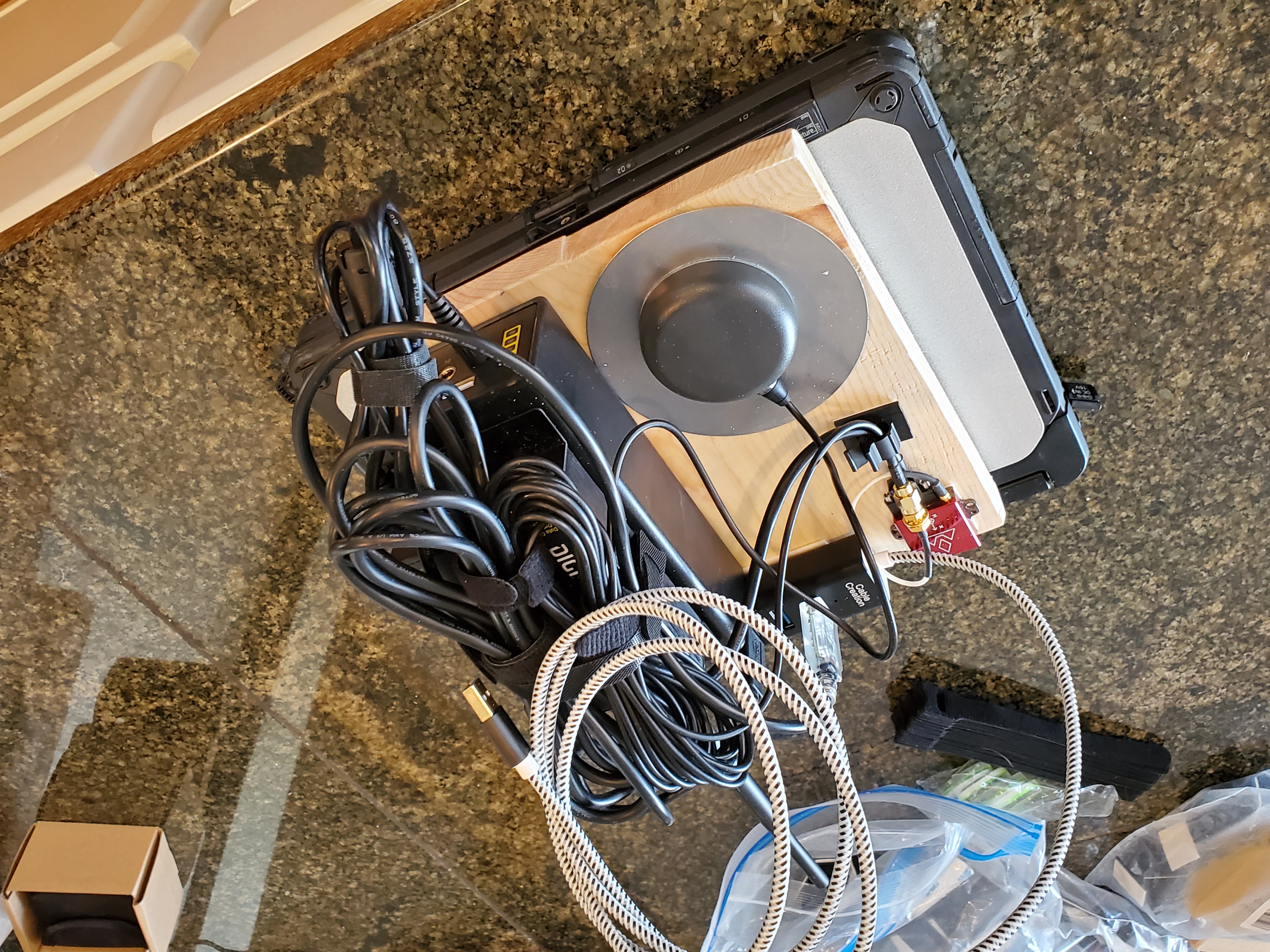
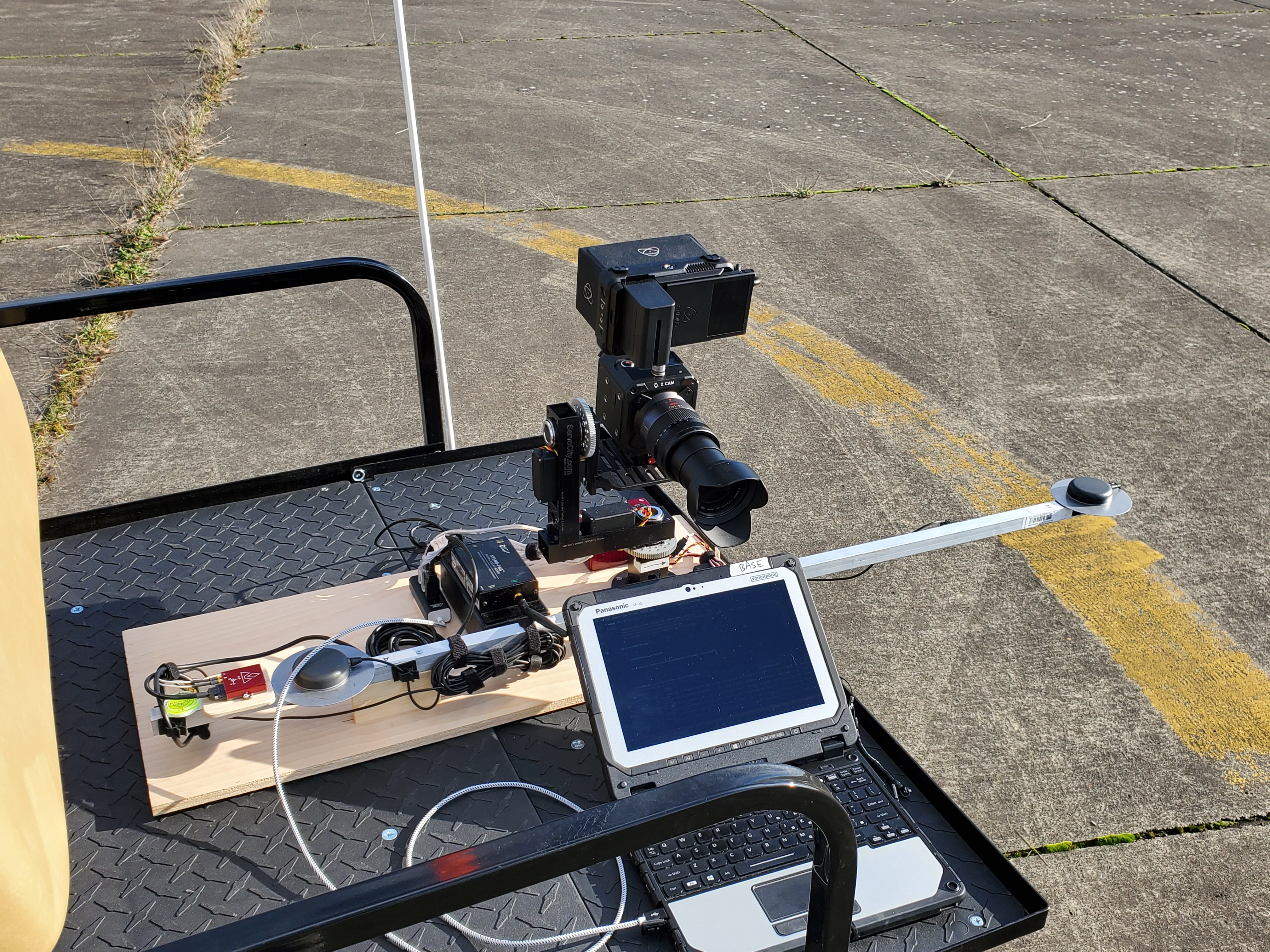
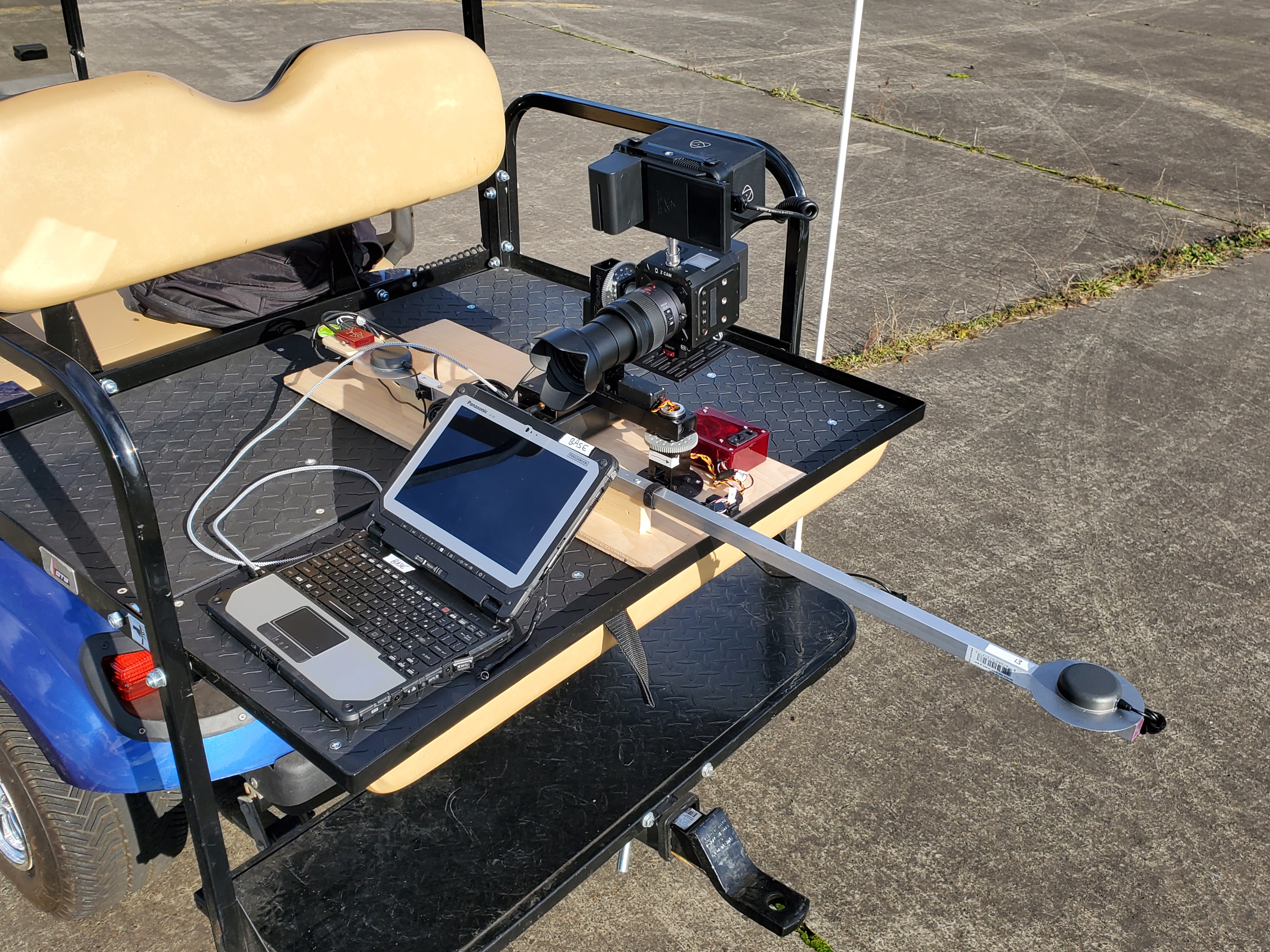
Ground Station
- Golf cart (yes, you can drive the golf cart while the system is in use and it tracks the plane)
- VectorNav VN-300 sensor
- Two hockey puck GPS antennas for differential positioning
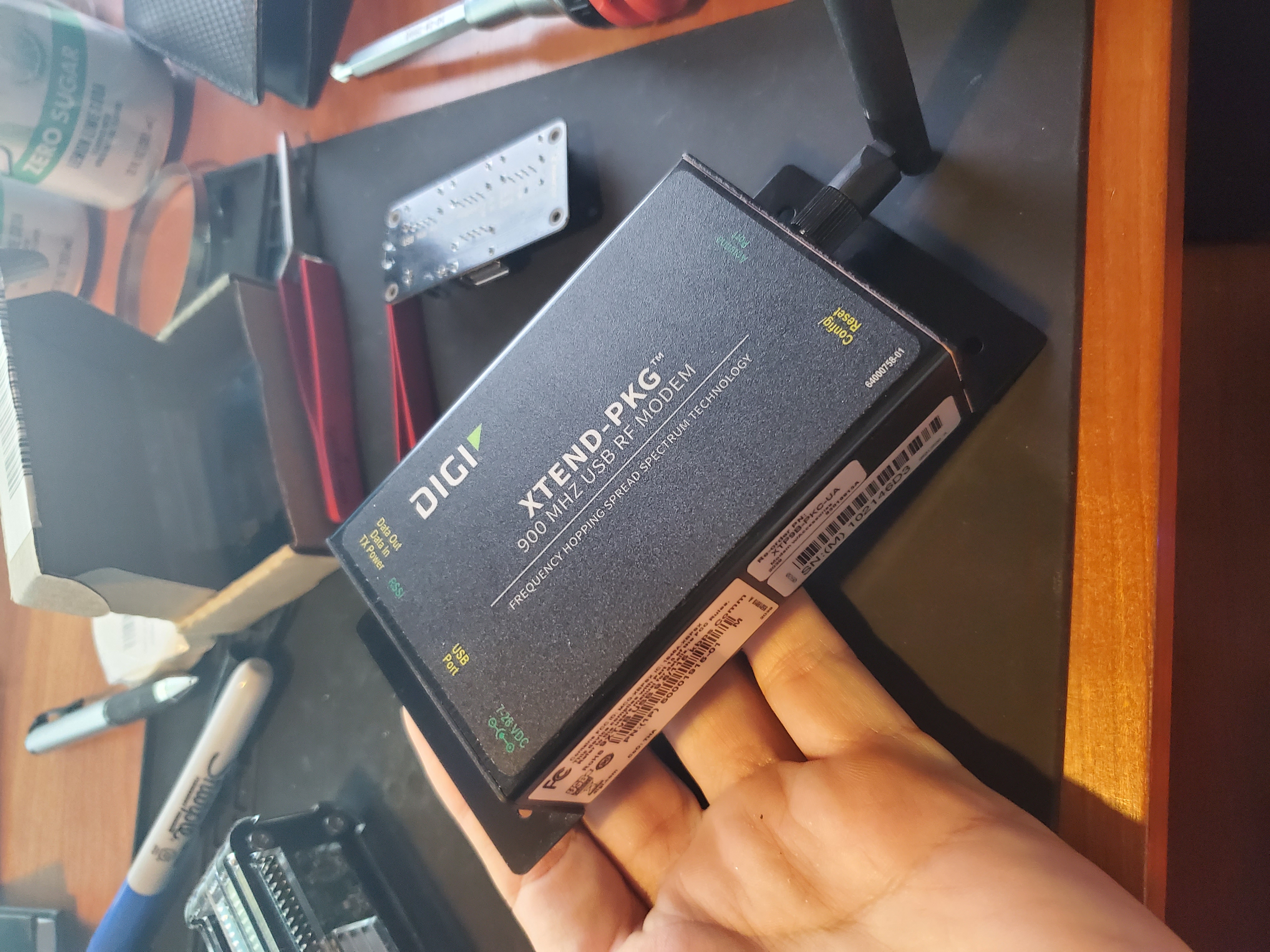
- A 1 kW transceiver from Digi (I tested this to several miles—works great)
- A UPS-style battery to power the laptop and transceiver
- A ruggedized laptop running custom software
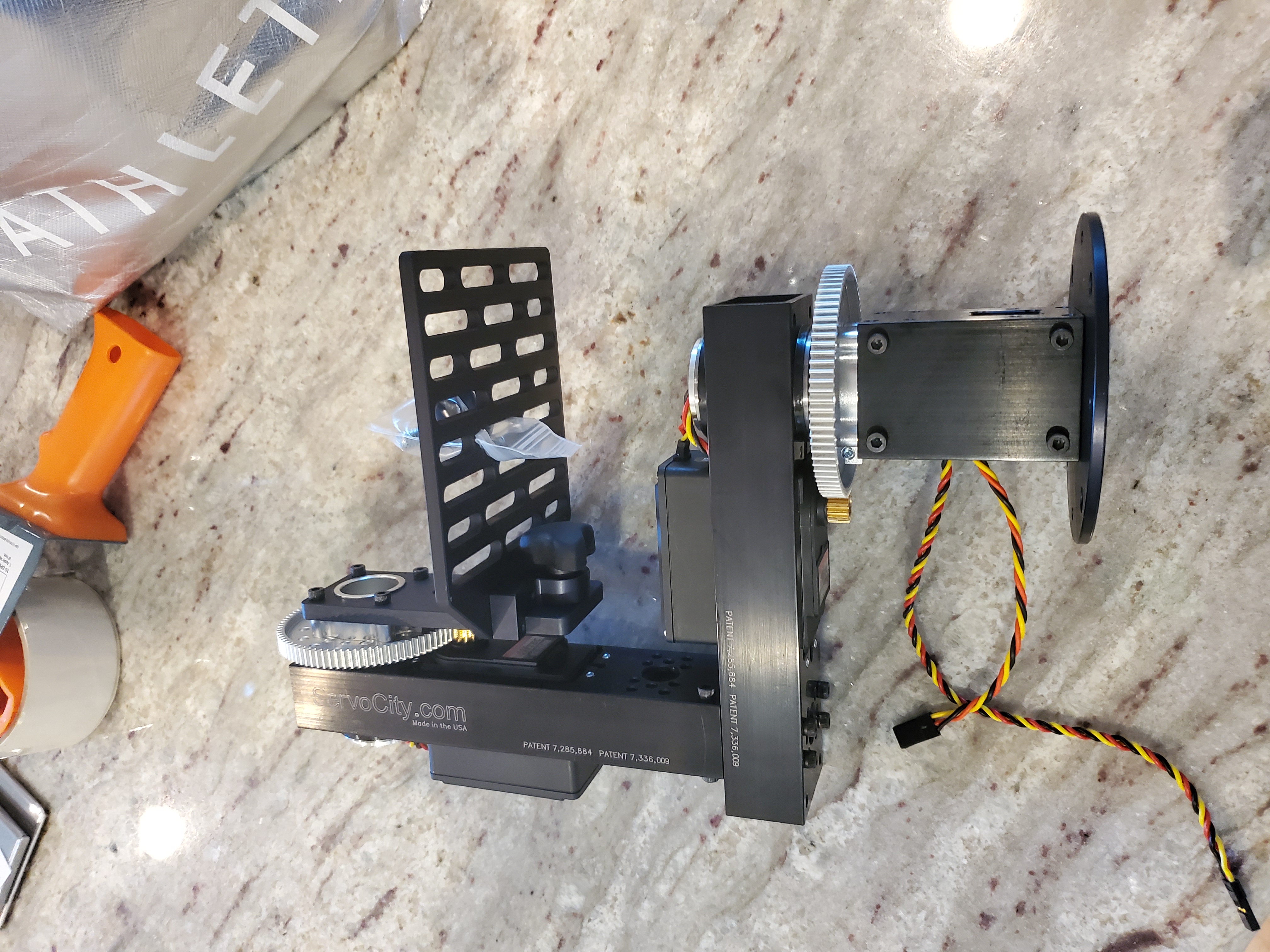
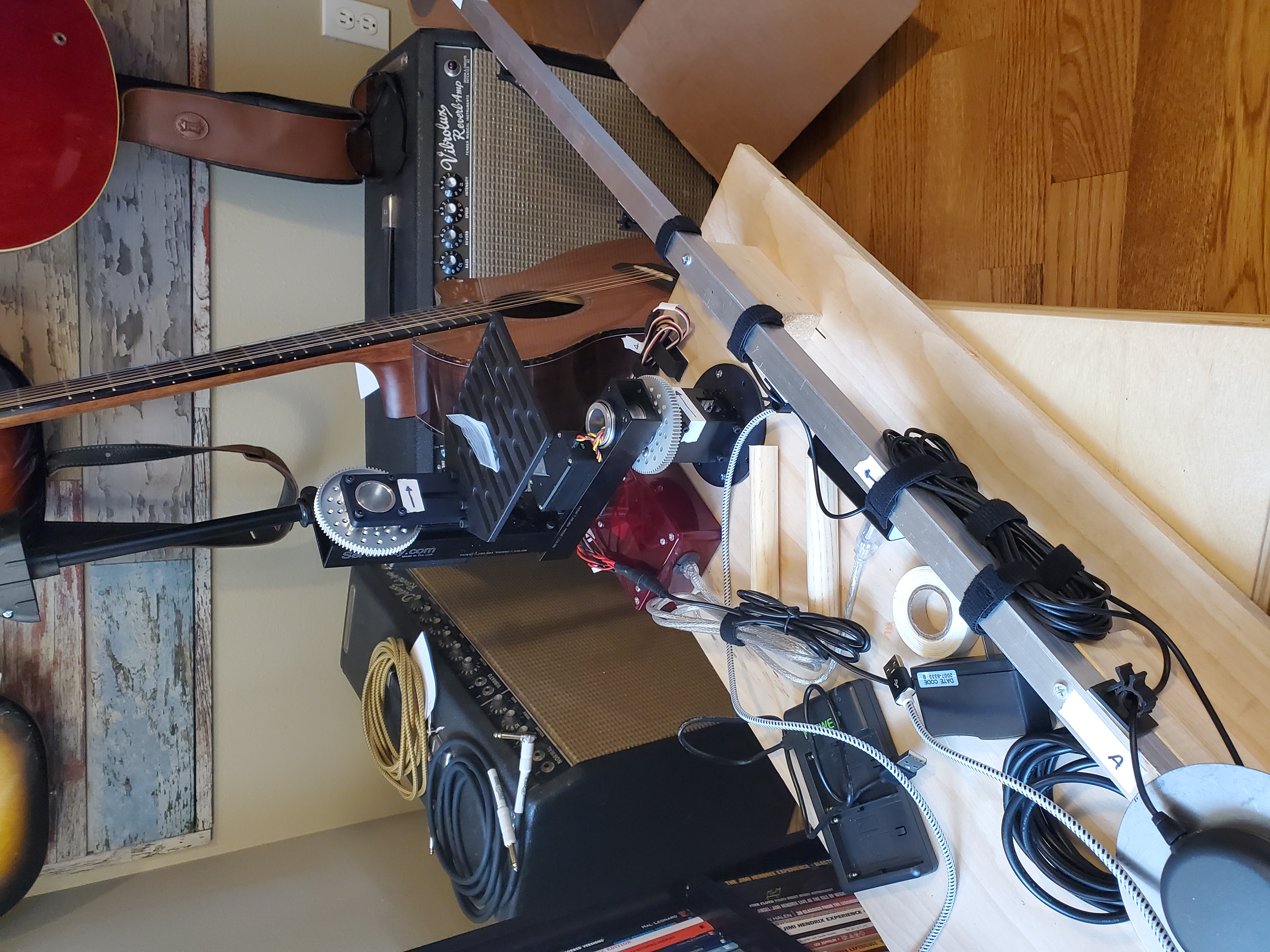
- A pan/tilt gimbal system from ServoCity with a camera
Aircraft
- VectorNav VN-300 sensor
- One GPS antenna (differential GPS isn’t needed on the aircraft)
- 1 kW transceiver
- Small UPS-style battery
- A computer of some kind—I started with a laptop but went to something smaller
How It All Works
At some point I’ll dig out the code and explain the details, but essentially:
- The ground station and the aircraft have to know where they are to a very high degree of certainty, which is child’s play with these sensors.
- The aircraft beams down to the ground station exactly what its airspeed and orientation is.
- The data has to be compressed because the bandwidth isn’t great.
- The ground station has to understand the curvature of the earth. The earth is not flat and it turns out it’s not even as round as you probably think. There are different earth models of varying degrees of complexity to choose from.
- The ground station uses basic trigonometry (complicated by the less-than-round earth) to determine what pan and tilt angle is needed to drive the camera gimbal.
Things Left to Solve
Some things that were left to solve but I didn’t get to:
-
Programmable zoom lens. I wanted a way to zoom the lens in and out programmatically so the aircraft would always take up the same amount of viewfinder area, but I couldn’t find a great lens that allowed for that. So I bought a great lens that had none of that capability and planned to get some servos attached to it. That would have worked but the calibration steps would have been complicated and error-prone. If I did it again I would start with the lens—that’s actually the hardest part.
-
Stepper motors for the gimbal. The pan and tilt platform is servo driven. I planned to use stepper motors and a micro switch so the gimbal could precisely zero itself. The servo solution doesn’t have high enough resolution for the job.
-
Miniaturized aircraft component. The component that goes on the aircraft could become very small with custom circuitry. I started going down that route, then decided to farm it out, then gave up when I didn’t hear back on any of the quotes I asked for. This is not hard—it just takes some effort.
One of the reasons this project stalled is that I got interested in AI and image processing. It’s still not possible to use image processing in real time, but there are image processing models out now that could do the job of MotionCrop. Image processing has always been an interesting area of study for me and I may return to this project some day.
Costs
The VectorNav sensors alone were about $5,000 each, though they would be less if purchased in bulk. The transceivers were about $500 each. The rest of the equipment was under $1,000 total, except for the computers which cost what computers cost.
When I started out I thought if I could build a device for $1,000 or so and sell it for $5,000 there would be a good market for it. Nowadays I think the costs would be in line with that. I’ve had experience with the BoxDaq which uses VectorNav sensors and costs a lot less, and the box used with AcroWrx has an even lower price point—so the costs of these sensors must have come down significantly.
The other cost is of course my time, but what is the price of a good time?
The Results
After some initial iterations where I changed earth models a few times and discovered bugs in my code, the system worked great. Every time I powered it on there was a bit of handshaking between the ground and aircraft station to sort out which way to point the gimbal. I originally was planning to mount the ground station’s VectorNav sensor on the gimbal, but I didn’t get to that because the coordinates were easier to understand from the debug output with the ground station mounted tangential to the earth’s surface. I had a few commands I could send from the ground station to the aircraft to monitor the status and control log output. I was planning to create a user interface for that, but that’s another project. So many times with projects like this you can get 90% of the way to a working solution and still have 90% of the actual design left to do, and that’s the case here. It works, but only for a user who understands everything about it.
Unfortunately, I don’t have the best photos and I have only two videos. I searched and searched and these are all the files I could find that are even close to publishable. The project did work, but life’s circumstances prevented me from getting into any kind of marketing mode about it. So it just sort of sat for a long time and now I thought enough time has passed that I owe it to everyone to share something about what it was about.
Videos
Here are the two videos I found. I uploaded them to YouTube where people watching my channel are probably asking themselves “what the heck is this???”
Thanks for reading this and I hope it gives you some ideas. To me, life is all about making things, whether it is a friendship, art, a new technology, a pretty aerobatic maneuver to draw through the sky, or this web site!
